Good Evening everyone.
I recently started working on the SatNOGS v3 rotator. It’s truly an incredible piece of engineering and I can’t wait to get mine going!
I’m not using the custom SatNOGS pcb. I’m using a standard Arduino Uno with a CNC shield with A4988’s, which has GREATLY simplified the project as they’re all off the shelf, preassembled, inexpensive components… The Uno, stepper drivers, stepper motors, and shield came to about $60CAD on Amazon Prime, and electronically everything was working within an hour of the parts showing up.
In order to do this I’ve made a few tweaks to the code to take advantage of parts I already have laying around…
I’m using:
Arduino Uno R3 clone
Arduino CNC Shield V3 with 4x A4988’s (only 2 in use) https://www.amazon.ca/gp/product/B016O7TD6O/ref=ppx_yo_dt_b_asin_title_o00__o00_s00?ie=UTF8&psc=1
Nema 17 Stepper Motors
https://www.amazon.ca/gp/product/B06ZXQXD9X/ref=ppx_yo_dt_b_asin_title_o01__o00_s00?ie=UTF8&th=1
Meanwell ELN 60-48D power supply.
Gpredict on Windows 10 PC
Rotctl
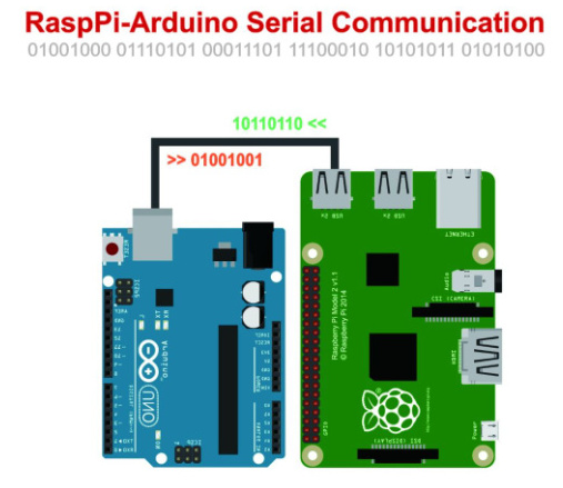
Currently I’ve modified easycomms.h to use Serial communications instead of RS485, which lets you connect the arduino to the pc directly without any adapter cables or modifications. I plan on adding the SatNOGS Pi Groundstation at a later time, my primary goal is to track satellites to enable capturing of HRPT.
I also had to modify the rotator_pins.h library to fix a few of the pinouts which changed when I used the CNC shield.
Here’s the pinout thats working for me at the moment. keep in mind this is just getting the servos moving according to Gpredict, I haven’t setup the limit switches or output pins for them yet.
/*!
* @file rotator_pins.h
*
* It is a header file for pin mapping.
*
* Licensed under the GPLv3
*
*/
#ifndef ROTATOR_PINS_H_
#define ROTATOR_PINS_H_

//#define M1IN1 10 ///< Motor 1 PWM pin
#define M1IN1 2 ///< Motor 1 PWM pin
#define M1IN2 5  ///< Motor 1 PWM pin
#define M1SF  7  ///< Motor 1 digital input, status flag for DC Motor Drivers
#define M1FB  A1 ///< Motor 1 analog input, current/load feedback for DC Motor Drivers

#define M2IN1 3 ///< Motor 2 PWM pin
#define M2IN2 6  ///< Motor 2 PWM pin
#define M2SF  7 ///< Motor 2 digital input, status flag for DC Motor Drivers
#define M2FB  A0 ///< Motor 2 analog input, current/load feedback for DC Motor Drivers

#define MOTOR_EN 8 ///< Digital output, to enable the motors

#define SW1 11 ///< Digital input, to read the status of end-stop for motor 1
#define SW2 9 ///< Digital input, to read the status of end-stop for motor 2

#define RS485_DIR 2 ///< Digital output, to set the direction of RS485 communication

#define SDA_PIN 3 ///< I2C data pin
#define SCL_PIN 4 ///< I2C clock pin

#define PIN12 12 ///< General purpose I/O pin
#define PIN13 13 ///< General purpose I/O pin
#define A2    A2 ///< General purpose I/O & analog pin
#define A3    A3 ///< General purpose I/O & analog pin

#endif /* ROTATOR_PINS_H_ */
So, now that I’ve got all the electronics working, I’m much more confident that this project is within my abilities. Need to source and order the rest of the V3 mechanical parts and find someplace to 3D print! I’m hoping to take advantage of the local universities professional printer… fingers crossed.
I plan on documenting the process as much as I can along the way and providing my version of a walkthrough once it’s all working.
I’m sure I’ll have more questions Regarding the 3d printing and hardware assembly soon… as soon as the parts start rolling in.
Thanks again for creating such an amazing project guys, lookin forward to being part of the community and being able to help!
