I’m an E.E. undergrad student who is very interested in the SatNOGS project. I don’t have much space nor money, so I’m stuck with a fixed antenna setup.
This gave me the idea of designing a single board that integrated filtering, preamplification (LNA), protection and diplexing (? optional). Kind of a “SatNOGS RF front-end” for RTL-SDR dongles.
What do you think about this idea? I think it’s quite doable, however I’m not sure whether such a thing already exists or you guys think it’s necessary.
Hey!! Nice idea!! I can help you to design and test it! In this issue you can find more details about the specifications of LNA. A design for 2m/70cm Diplexer from community. I think that we can use the diplexer circuit in order also to filter the signal (2 BPF in parallel).
I love the sound of this project.
I am just in the middle of getting a fixed dual band station setup and am having all sorts of LNA and Diplexer issues.
To have a proven all in one solution would be fantastic.
Great! Having specs for the LNA is a very good start. I think a discrete diplexer as a filter can be a great option. Those mini-circuits band-pass filters look nice, but are also quite expensive, especially if we’re going to need two of them. Do you think it’d be better to use those pre-made filters (easier/expensive) or to design and build our own (harder/cheaper)?
I am more inclined to build a discrete filter as I live in Brazil and the more generic the components, the easier/cheaper to source them, especially if I can buy them from China
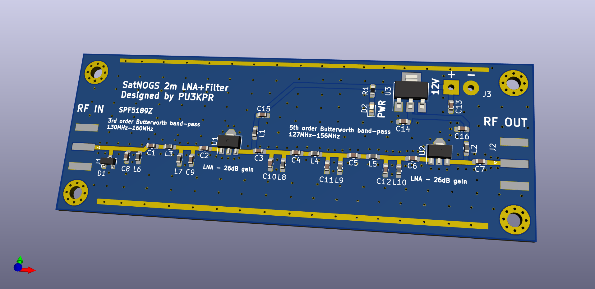
So I started off by building what’s going to be the most useful for me right now: a 2m band LNA + filter. I’m planning to build a no-rotator station and so I need lots of gain and filtering.
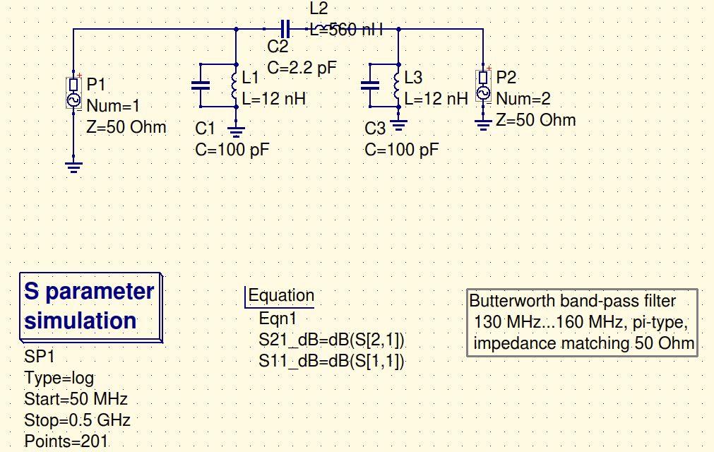
I started off by using QUCS to design a basic band-pass filter for use before the first LNA. This is to remove any possibility of forming intermodulation products on the output due to noise (bear in mind I’m 3km away from a 246kW TV station). I designed it with a slightly wider -3dB point because I wanted the filter to be tolerant to component variations.
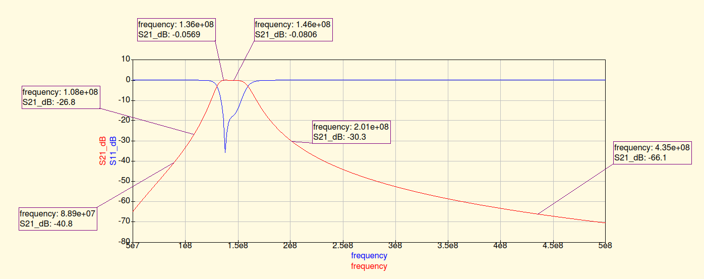
As you can see, it’s performance is not stellar, however it’ll probably be adequate as a pre-filter.
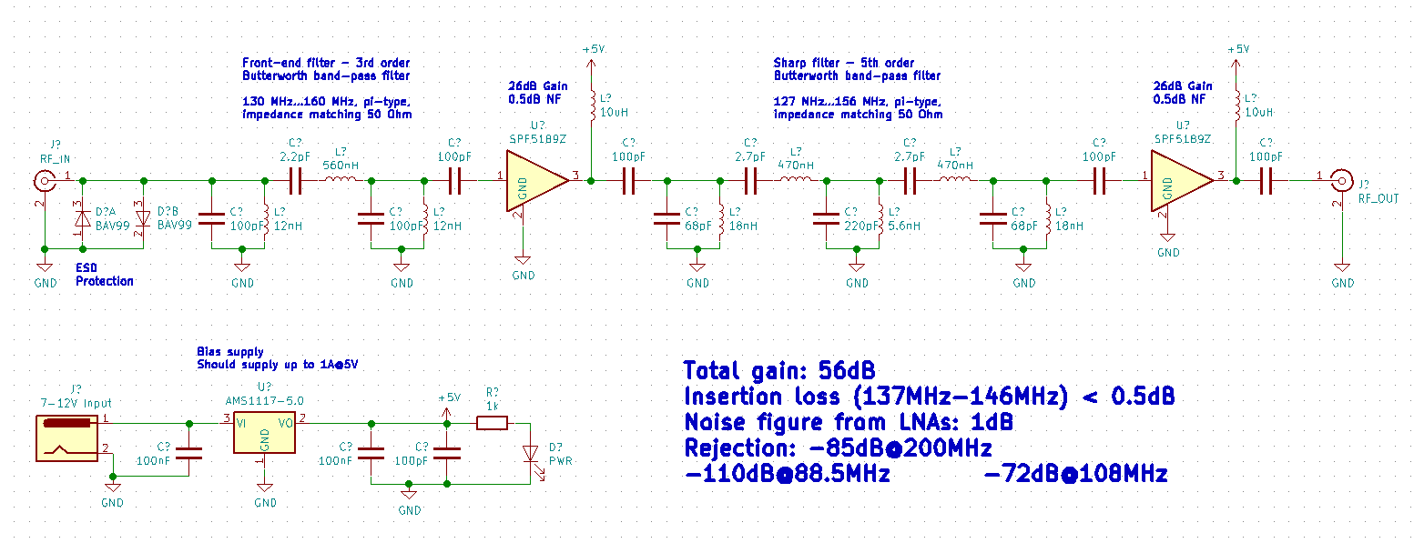
After this filter, I put a DC block capacitor (is it necessary?) and a SPF5189Z, because they’re cheap and easy to buy online. They should provide around 26dB of gain at these frequencies according to DD1US.
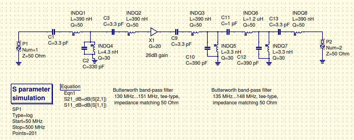
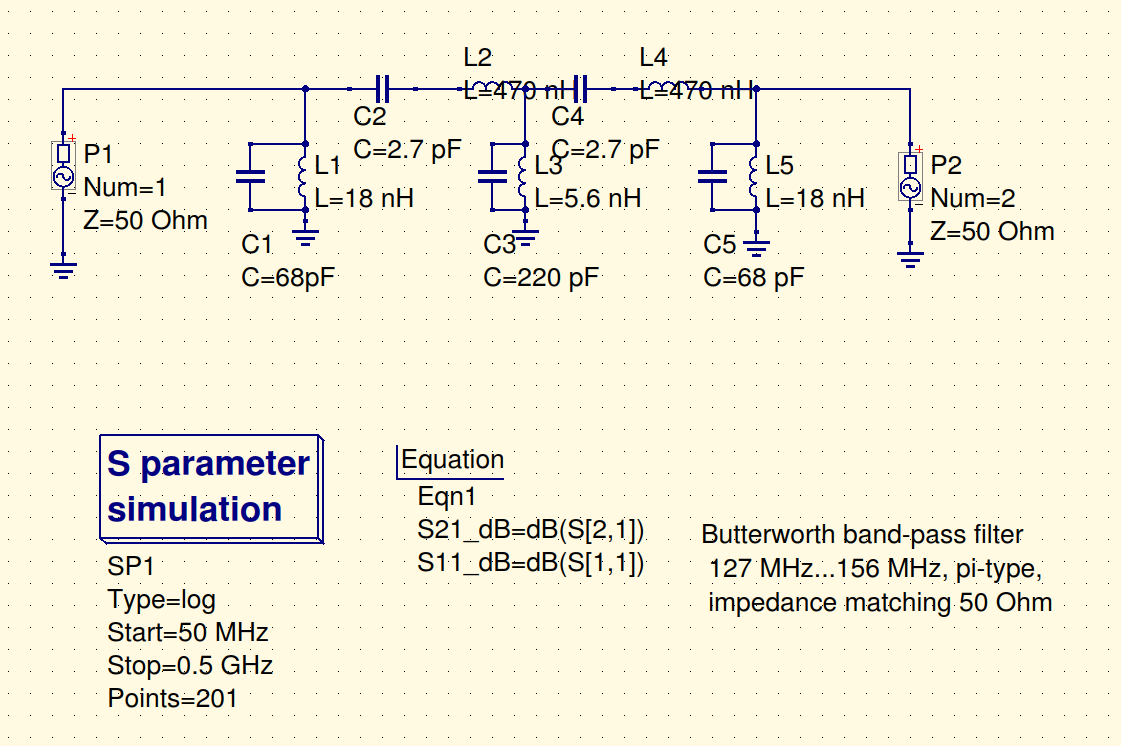
After the first LNA, the actual filtering happens. I use a 5th order butterworth filter for this.
Finally, the output of this filter is fed (through a DC block?) to another SPF5189Z that provides another 26dB of gain. This is the final schematic, complete with bias supply and ESD protection:
What do you think about it? Criticism is not only allowed but encouraged
(This doesn’t have a duplexer, however I don’t think I have money to install another antenna anyway. I plan on using this with a QFH to receive NOAA and amateur satellites.)
P.S.: How can I move the component labels away from them in QUCS? e.g.: L2 and L4
4x M2.5 mounting holes, total size 95x35mm. Using 0.825mm coplanar waveguide (assuming 0.8mm FR4) to achieve 50 ohms impedance. SMA edge launch connectors. Support for metal casing/shielding.
This is looking really good.
I almost want to say that its clear enough that I could hand solder this which makes it a very attractive project for me.
Great work.
Update: as suggested on reddit I will try to redesign the board using Mini Circuits modules. I have already requested samples of the RBP-140+, RBP-440+ and PSA4-5043+, the same LNA used in the LNA4ALL.
Hey! Nice work!!
Why you want a gain like ~52dB?
You can add the option to power the board from the RF-OUT by using Bias-T for example from RTL-SDR. In QUCS you can use s-parameters of all components (if you need any help let me know). Also you can design the PCB in order to place it in a weather - proof box that you can find easily in china.
In hackerspace here in Athens we have spectrum analyzer and VNA in order to test it.
I need this gain because I want to extract as much performance as I can from my omnidirectional antenna. I believe that the multiple filtering and amplifying stages can help me do more work with a suboptimal setup. Therefore, I need this gain so I can cope with the feedline loss of a suboptimal cable (RG6) and insertion loss of all that filters (could be quite high, according to a discussion I’m having on reddit).
I’ll look into these weather-proof boxes. I’m also thinking about buying myself a NanoVNA so I can test them myself. I’m still reviewing it’s performance though.
Mini Circuits gave me an update saying that they have problems shipping to Brazil, so I’m not sure whether I’ll be able to get my samples Therefore, I’m (at least for now) stuck with a discrete filter.
The aim is to reduce the noise figure of the system, while ensuring any resultant signals arriving at the receiver at above its noise floor. Any more level than that is a waste.
If you can see a rise in the noise floor of the receiver when you insert the preamplifier, then you’ve done all you need to do. Adding any more gain at the preamplifier will give no more improvement in performance, and may just result in more IMD products being generated.
Unless you have seriously bad coax, I’m pretty sure that the second amplifier will not be required. I don’t think ‘adjustable’ gain is necessary, but being able to bypass that second amplifier is going to be the go for 99% of use-cases.
To be honest, I probably would have stuck with using discrete components for your bandpass filters. Use physically larger components to reduce losses. I would suggest using a fairly wideband filter ahead of the preamp (less losses which directly add to your noise figure), and then a narrower one after (where it doesn’t impact noise figure as much).
While using Minicircuits modules is a convenient way of doing things, they are costly, and may not have the performance you really want. For example, the RBP-440 has a passband between 410-470 MHz - this means that you are going to pass through land-mobile traffic between 440-470 MHz, which is probably better off being filtered out.
Finally, as an alternative to the PSA4-5043+, the PGA-103+ (still from minicircuits) is a good option: https://ww3.minicircuits.com/pdfs/PGA-103+.pdf The key point is that is has a better IP3 (~40 dB vs 32 dB), while providing similar gain and noise figure performance. This means it will handle large signals better, so you move your bandpass filtering from the input to the output of the amplifier.
Okay, got my samples denied because I’m Brazilian and Mini Circuits hates our post office losing their parcels. Back to a discrete filter.
@DL4PD I’ll for sure keep this as a stretch goal, however I’ll first try to solve my immediate problem. Thanks for your suggestion!
@vk5qi Okay, so the general consensus is that the two LNAs would provide too much gain, so I’m scraping that idea. Anyone who needs more gain could add another LNA externally later anyway.
You’re right about the Mini Circuits modules, I’m just afraid of having to tune a filter without proper equipment, so they seemed attractive.
I’m now searching for low-loss inductors. So far, I have find this series from Abracon to be interesting, as they have relatively high Q (min 50), are reasonably accurate (± 2%), cheap (~$0.22/single) and easy to source (I can in a single order buy PCBs from JLCPCB and components from LCSC). Capacitors and other components could also be bought from them, only the LNA would have to be sourced externally. It would come almost as an “on-demand” kit.
The PGA-103+ looks promising, however I’m thinking of sticking with the SPF5189Z as I can’t order from Mini Circuits anyway and the SPF5189Z only has a slightly lower IP3 (~41dB vs ~38dB). Also, the latter are quite cheaper and easier to source from AliExpress.
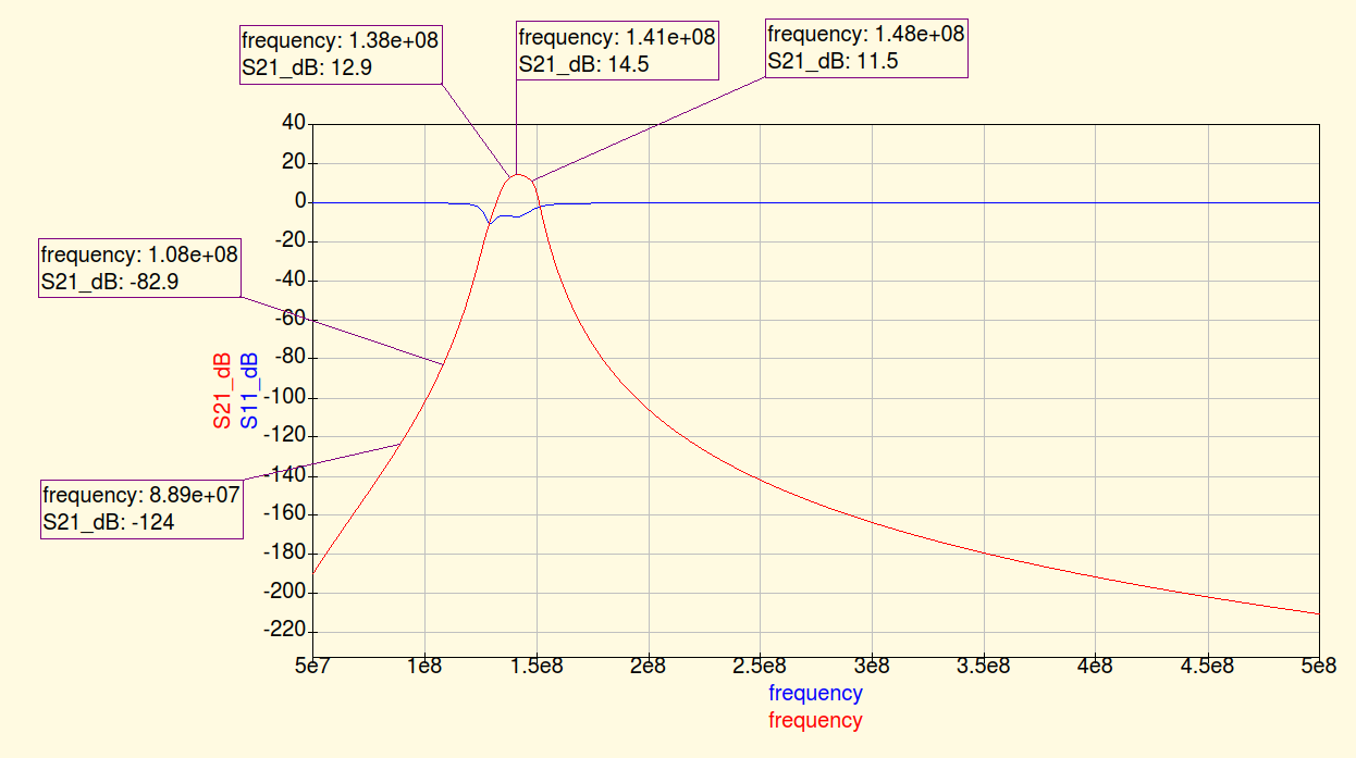
I’m now getting the hang of QUCS and trying to minimize losses as well as making the filter tolerant to component variations. My biggest problem now is that I can’t make the insertion loss lower than ~5dB (!) even on the first stage, considering Q=50 for the series inductors (as they’re larger) and Q=30 for the smaller, parallel ones. Any suggestions?
As you can see, the insertion losses of both filters are significant, however when adding the LNA we still end up with a gain of 13~14dB over the useful part of the 2m band. The roll-off is quite sharp too, which might be a problem with the tolerances I’ll be working with.
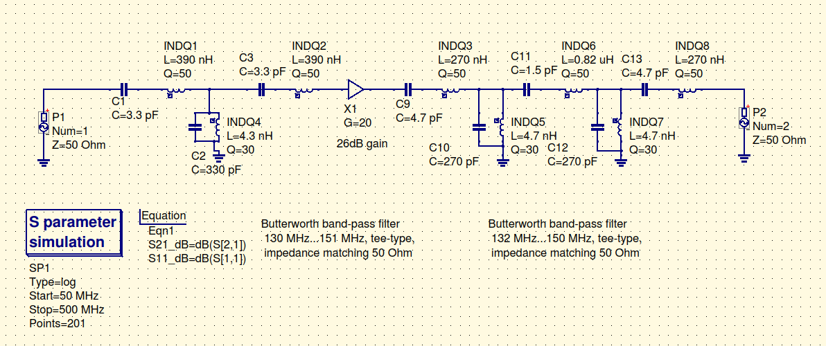
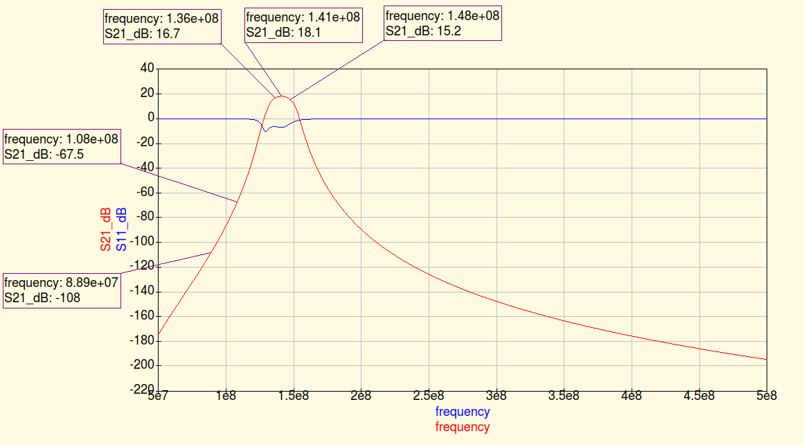
Widening up the second stage gives us quite nicer results:
Given the high IP3 of the amplifier, I would suggest completely removing your input band-pass filter. The insertion loss of that filter adds directly to the noise figure of your system. Only use band-pass filtering in front of the amplifier if you have sufficiently large signals at the input to the amp to cause IMD products to occur.
Hmm… If you can ensure enough isolation between the output of the amplifiers through the diplexer, then I’d say ‘yes’. That’s pretty much how my station at home is running, though I have 2 separate antennas, 2 separate masthead amplifiers, and then a diplexer just before the SDR.


 Therefore, I’m (at least for now) stuck with a discrete filter.