Hello, German!
Thank you for your interest. I’m ready to share all the info. But my project isn’t very orderly now. A few words about this.
Motivation:
investigate the possibility of using free or opensource software to calculate microwave devices instead of HFSS, CST, FEKO, etc.
use of cheap and readily available materials
receive pictures from meteo satellites, because its fun,I think, everyone loves pics, especially color
try to make a system similar to a digital antenna array, consisting of two antennas and two rtlsdr receivers synced from one oscillator
A significant difficulty is access to a network analyzer, but our frequency is low, then there are relatively cheap devices. There may also be a problem with the presence of a 3d-printer.
For calculations I used the onelab (gmsh+getdp) software. ./models/Antennas/mstrip.pro is the reference design. For writing a project I used the python bindings gmsh and pygetdp. But I think, it’s worth giving up using pygetdp, because this project is crude and it’s easier to use getdp language. In my opinion the syntax of this language is one of the ugliest.
Here’s repository of antenna project. Its code is very dirty and non-pythonic. There are all dimensions and calculations. https://github.com/ivantaran/mspa
Unfortunately I don’t yet have enough time to lead this project to be fully documented and clearly coded. But if you ask me questions, I’ll be glad to answer any.
Thank you very much Iván, for sharing information.
I really did not know the Onelab project, I am going to get into the subject, since I find it interesting to use modeling software that is not paid.
On my side the interest, at this moment, is for the UHF band and to be able to achieve a constellation of antennas that can be switched, I fulfill the role of a rotor (without being it).
As for, I study this a little better, I will not hesitate to consult you.
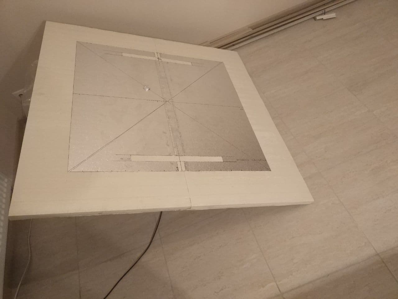
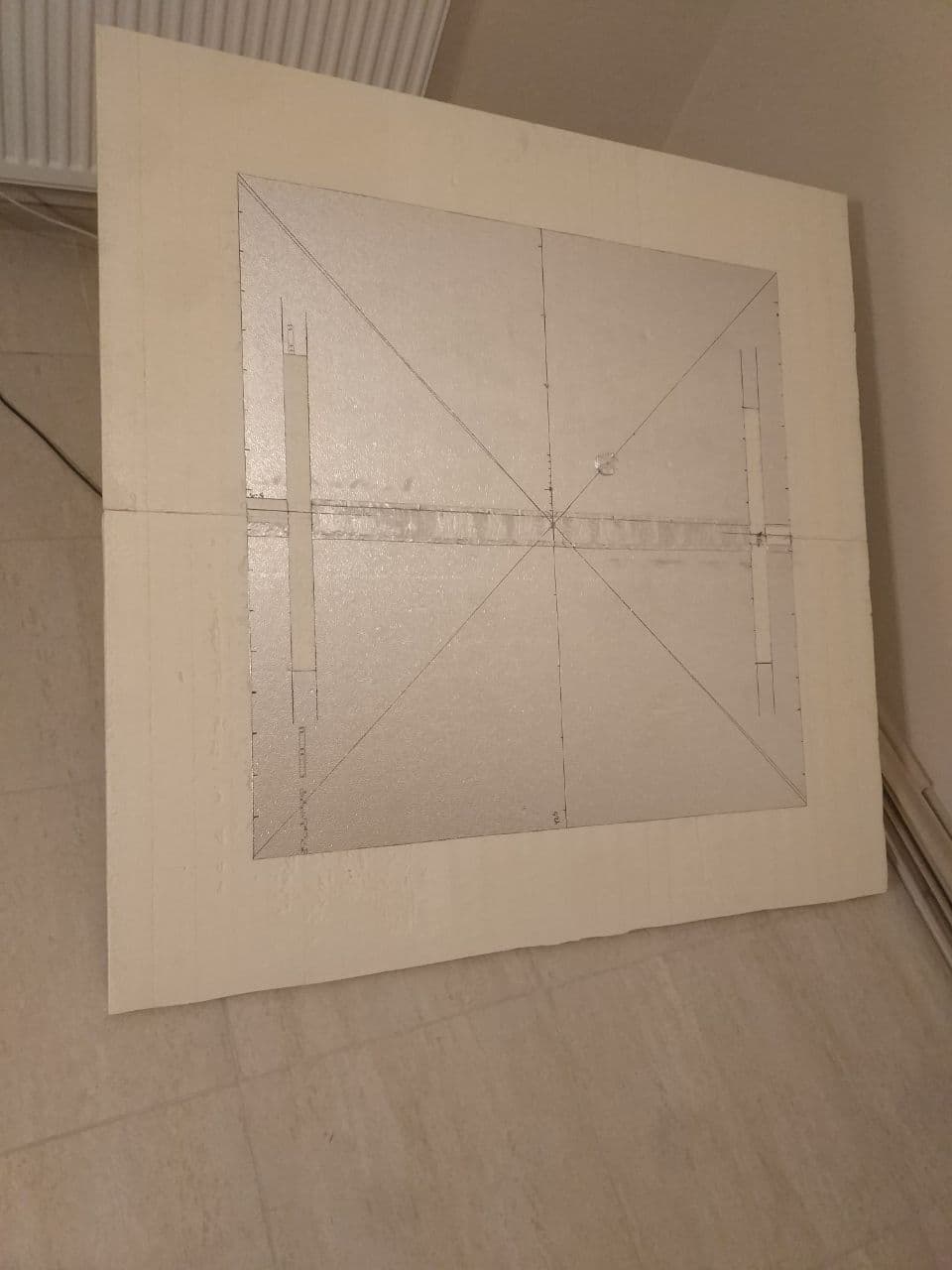
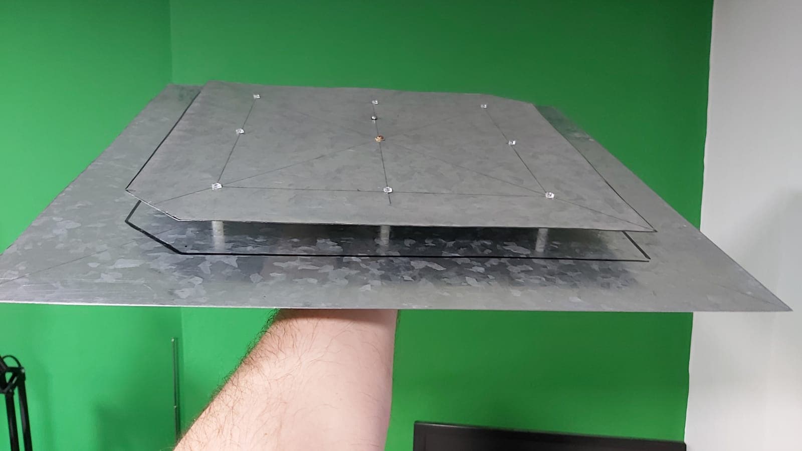
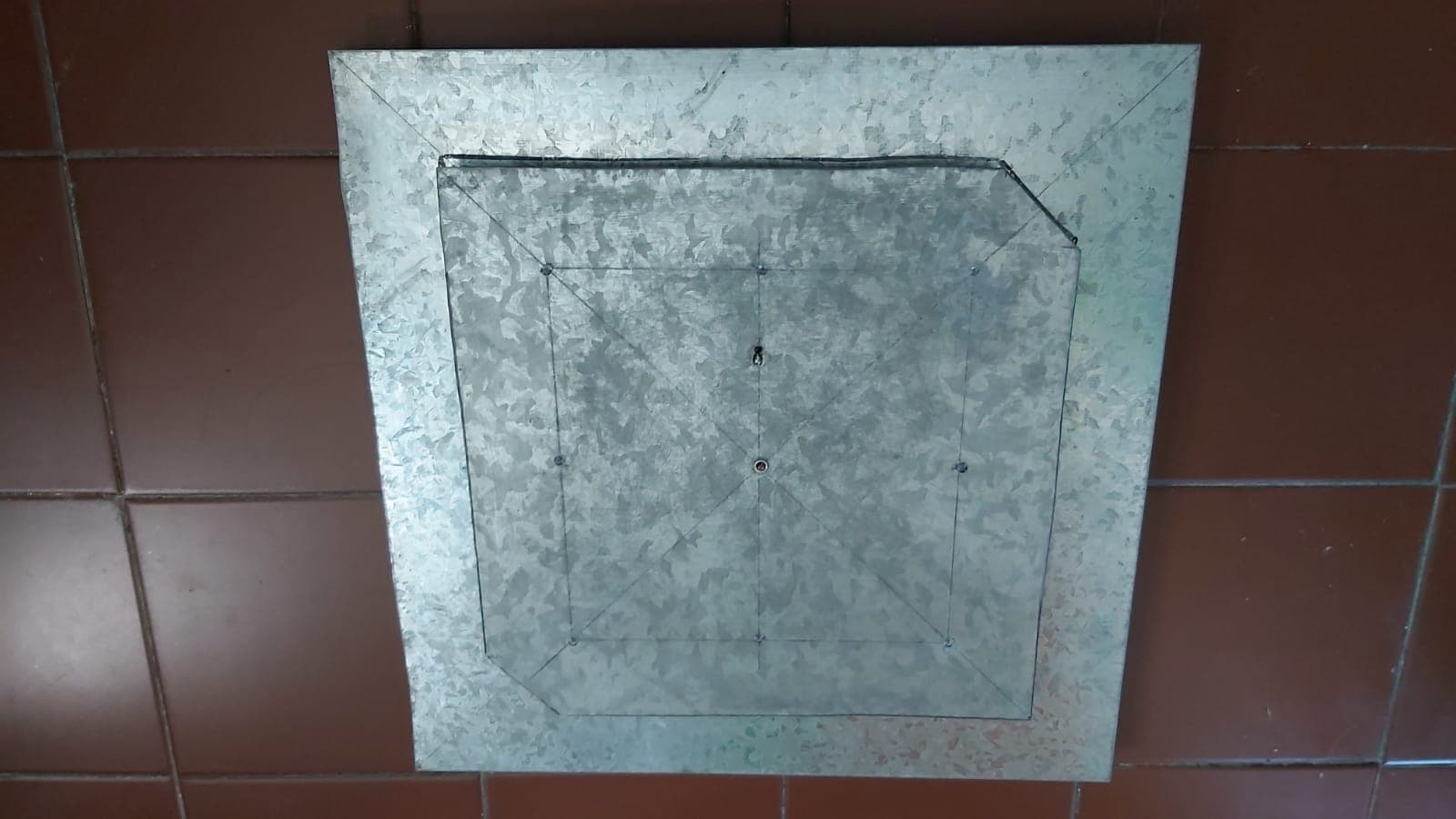
Hi, after some time of researching and looking for what I could do for UHF, I decided on a Patch type antenna model. Which I built and am testing, with good initial results. I leave some photos so you can see the model, if anyone is interested I can pass the measurements (I have to pass the doc to English beforehand).
I have not had much time to test it as I would like, but as characteristics that stand out, it is mainly very low noise level for the city (I am in the middle of the city of Buenos Aires - Argentina) and the reception angle was +/- 45° of Elevation with the antenna pointing to the zenith.
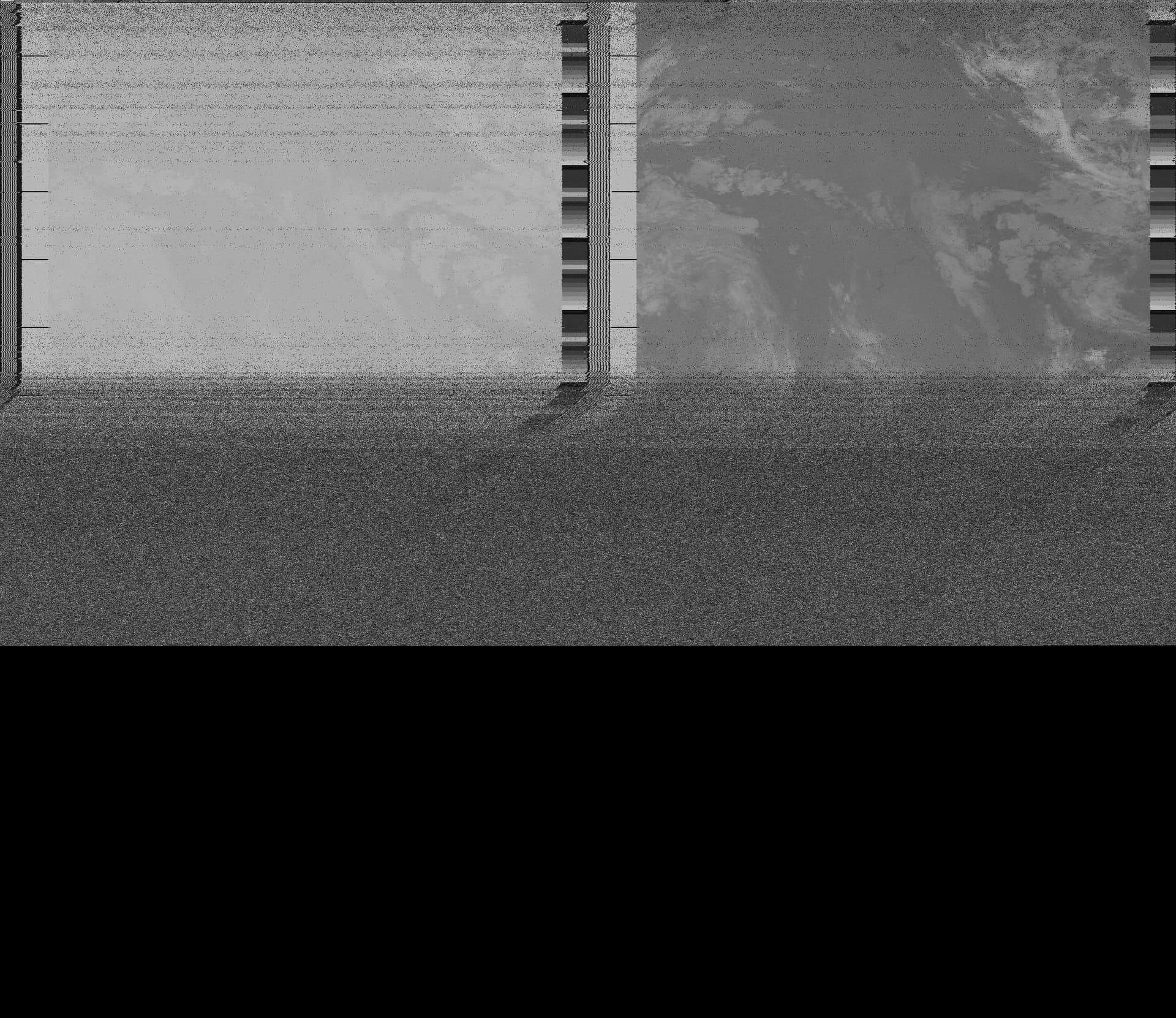
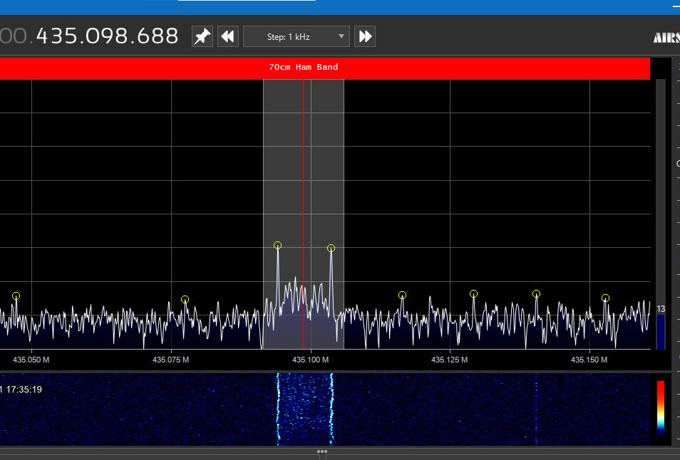
I leave you a capture of the reception of the Falconsat-3, passing over the zenith, using an SDR Nooelec Smart v4, without LNA and adjusted with a gain of about 20 dB (the noise floor in the image is at -80 dB ).
Hi @ivantaran - the Falconsat-3 trace looks good.
I am interested in building your antenna and would be interested in seeing the calcs’, please?
Is there any particular reason you used what looks like galvanised steel sheet?
ONELAB looks interesting.
Hi @m0roj. Galvanized sheet UHF antenna is the work of @gpagliaroli. I think, that this choice is due to the availability of this material and the ease of its processing. Please German correct me if i’m wrong.
Thanks to the information provided by @gpagliaroli, I can try to calculate UHF antenna in OneLab, if I find the time.
Hello @m0roj, for the calculation I relied on the one for a rectangular patch type antenna, with Coaxial feed.
As an initial link I took the design and conclusions of VK6YSF, which can be seen in the following link: https://vk6ysf.com/patch_Antenna_435MHz.htm
In which there is a very good description of the pros and cons of this type of antenna for UHF and of course details of its design.
Due to the type of material used, it was a matter of practicality, with what I had at hand, but surely using aluminum as a material is better for the outdoors.
Thanks @ivantaran for making the clarifications and I hope you can do the simulation to improve any detail.
Any question, do not hesitate to let me know and I will answer as soon as possible.
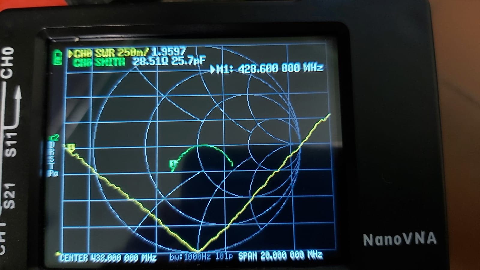
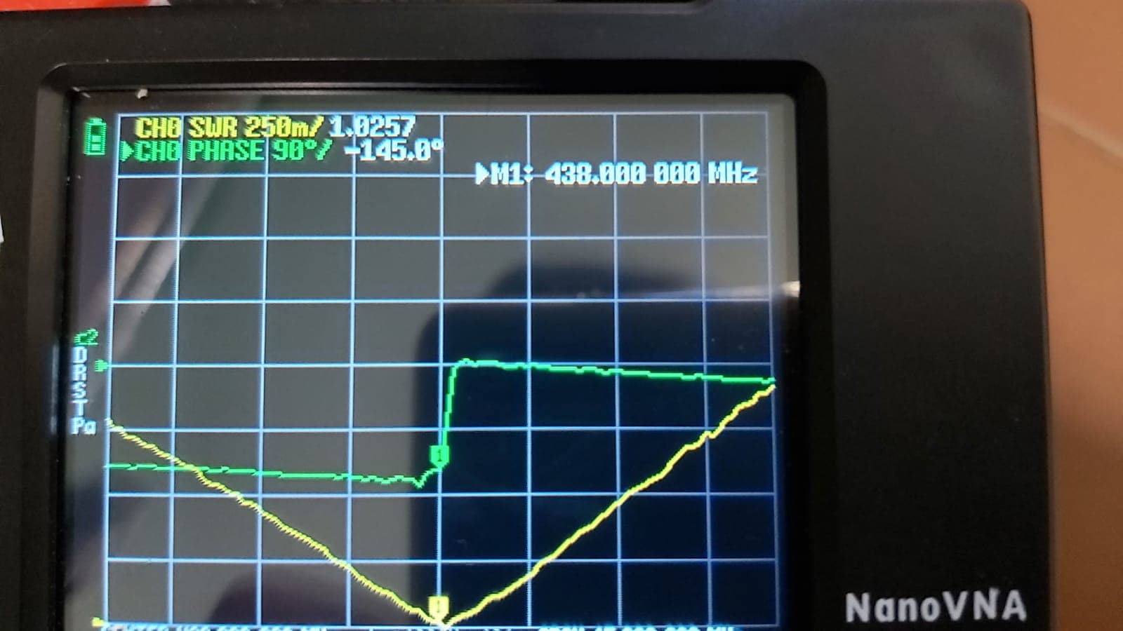
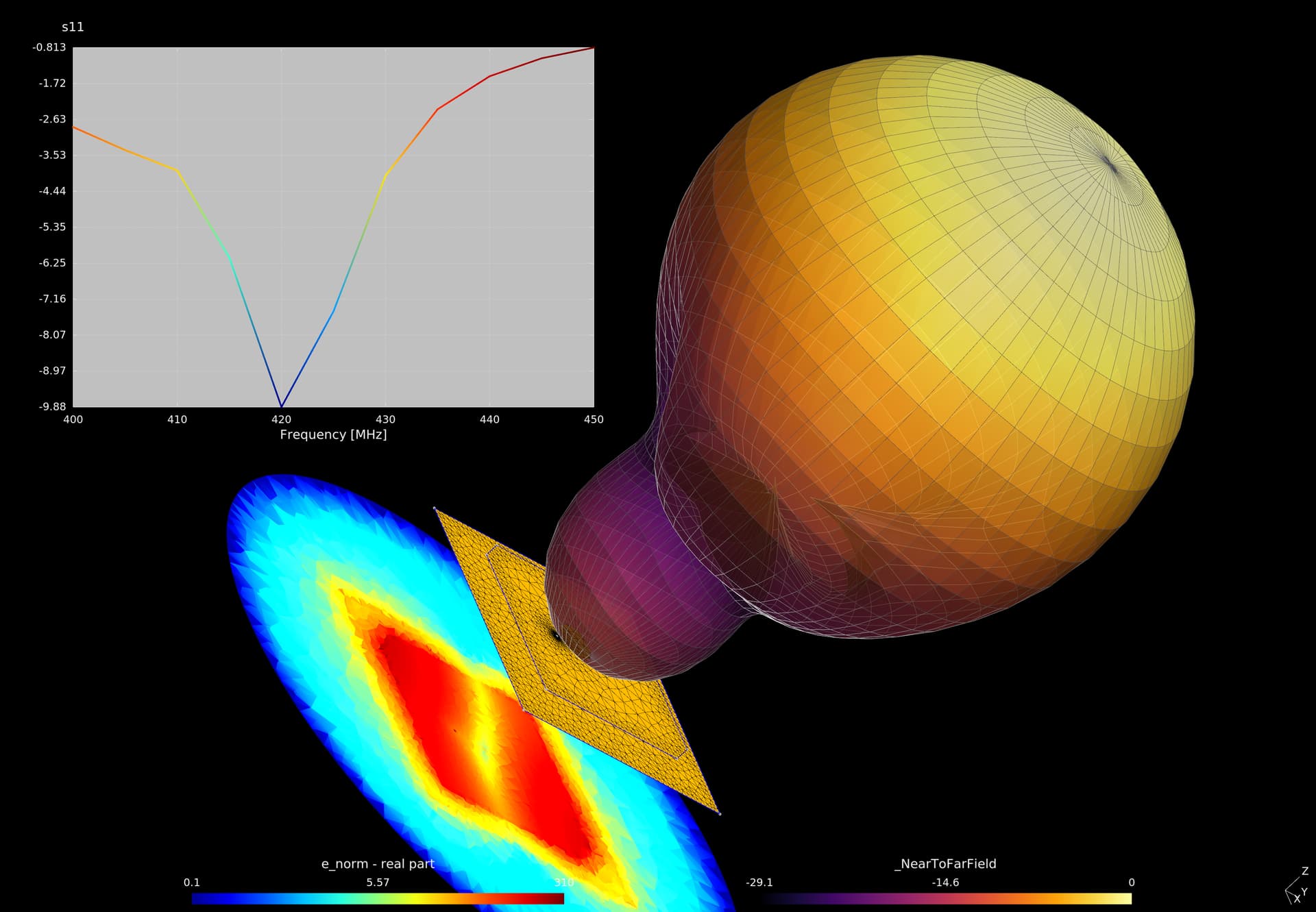
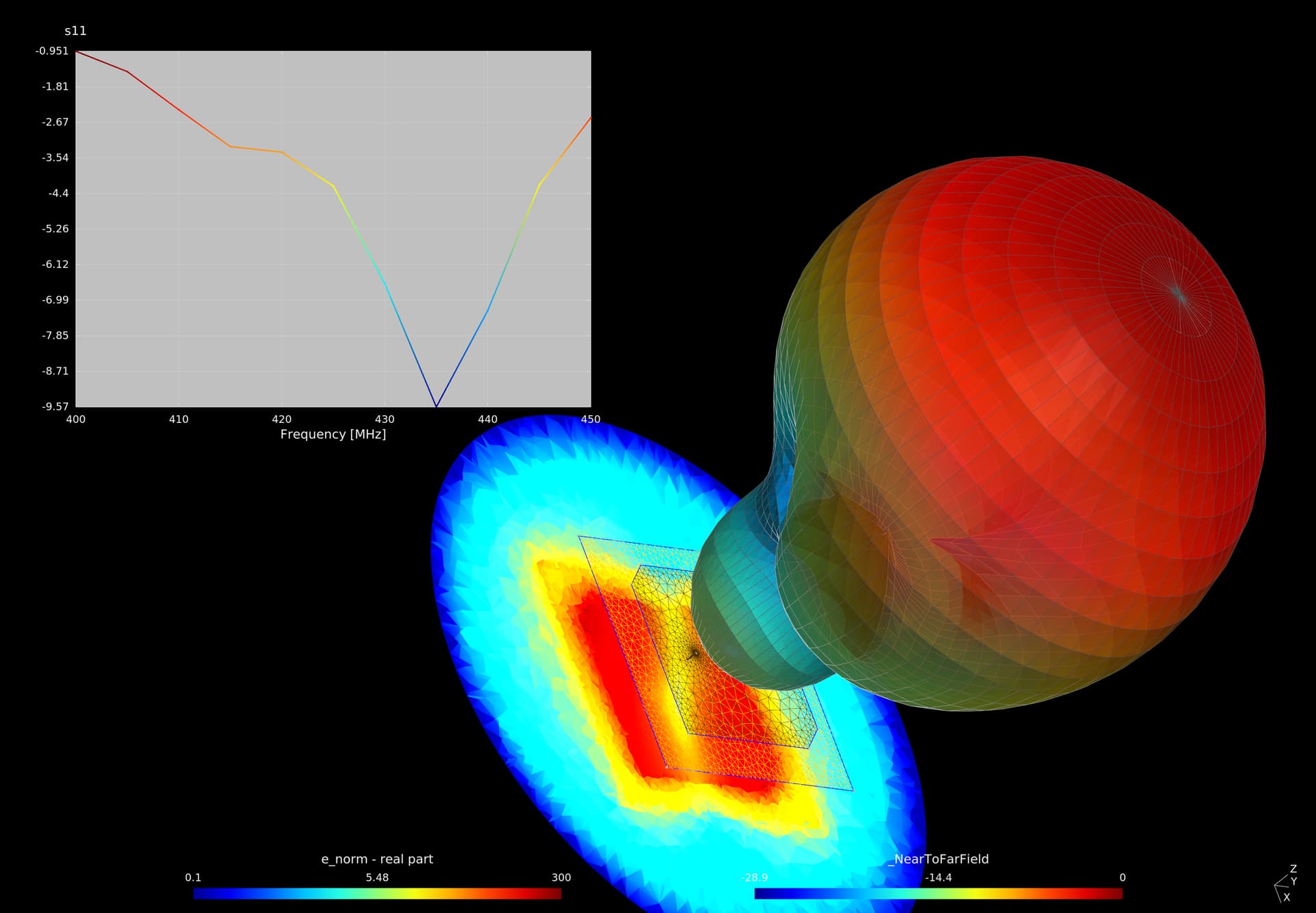
There is a resonance at 420MHz. It may be due to my modelling mistakes (e.g. mesh size) or imperfections in the model (absence of standoffs, screws…). But if I reduce the patch size from 320mm to 310mm, then resonance is around 437-438 MHz.
I agree that the difference in resonant frequency is due to some imperfections in the modeling, and how it looks a few millimeters make a difference.
But beyond that difference, the radiation lobe and the resonance curve and the bandwidth can be seen very well, I understand that they coincide with the result that I have obtained in practice.
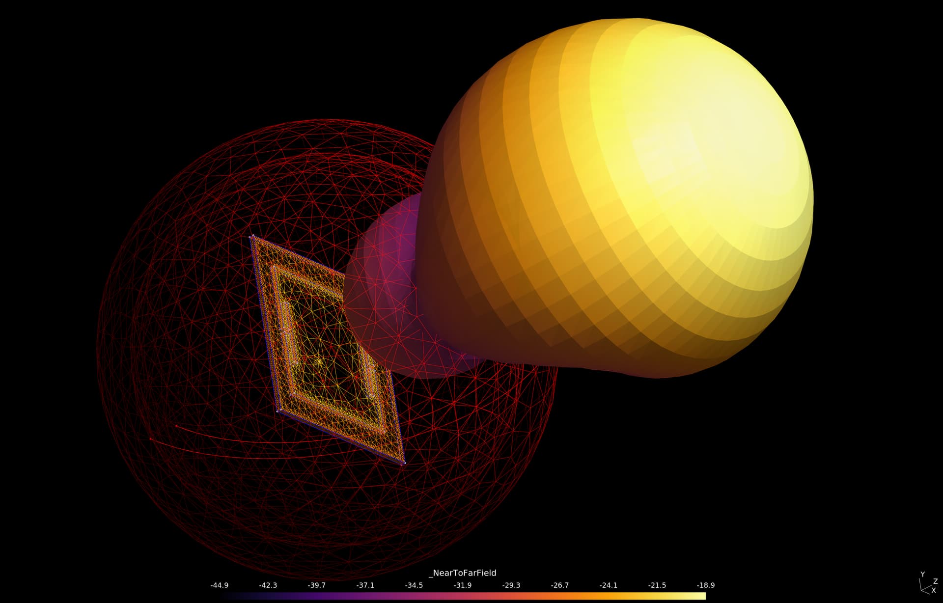
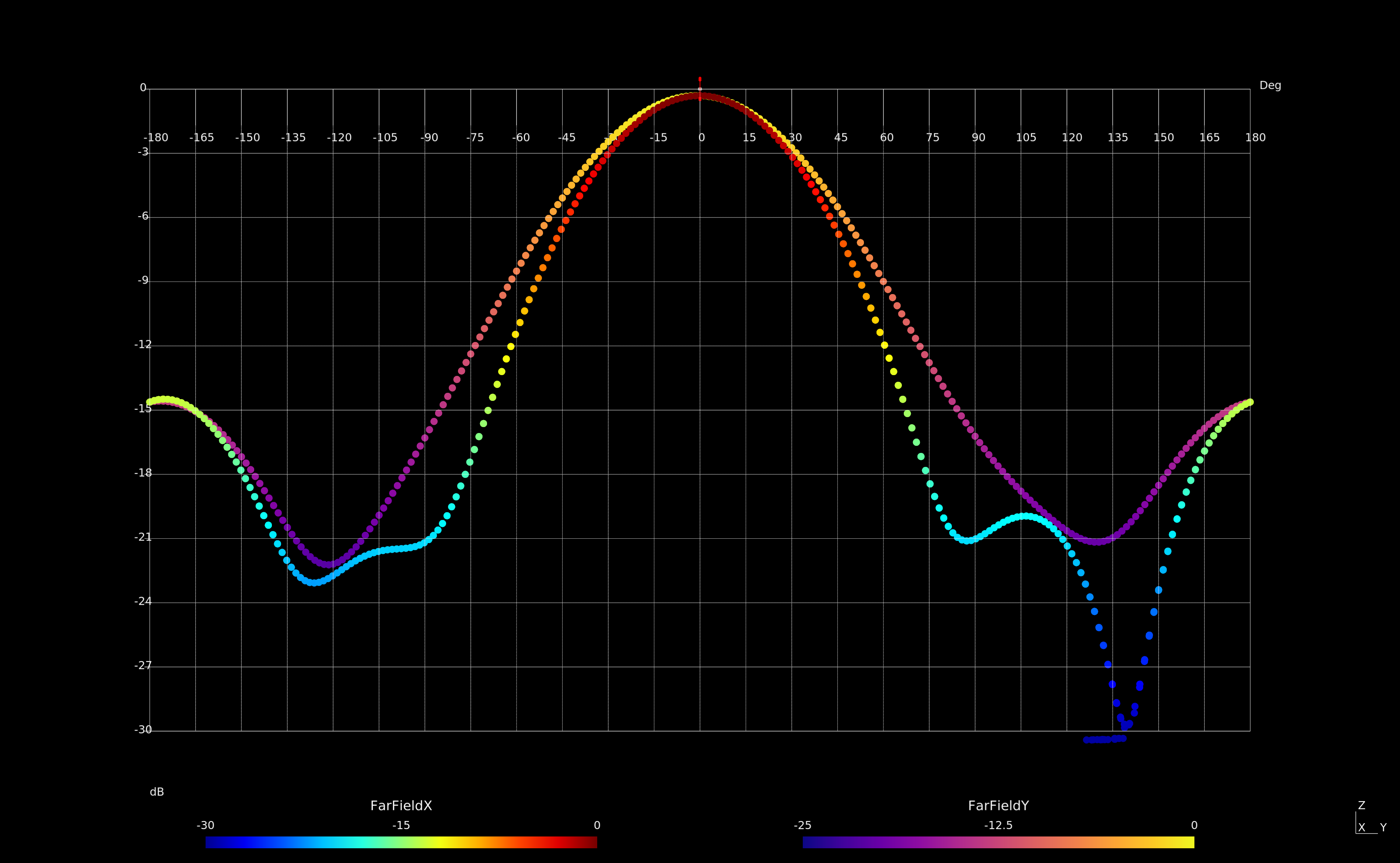
As a detail in the simulation, can the angle covered by the radiation lobe be calculated? (in my practical tests they have given me as a result +/- 45 ° with respect to the center).
I plan on trying to build on of these to use for my station, since I can’t seem to get my turnstiles working properly, (probably the phasing cable) and I never got one I order at one point, (got lost in the mail some where in Ney York.).
Unfortunately I can’t help you simulate the polarization thing, let’s hope to see if someone can help you with that.
Can you explain the radiation angle curve better to me? if I cut -6 dB it matches what I see in practice, is it correct?
I have checked equations of ‘near to far field’ conversion and there is no 3dB problem with 20.0*log10(amp) or 10.0*log10(pwr). But the likehood of error is present in other places as well.
Can you describe how did you got the beam width?
Why LHCP?
From what I have read we are supposed to use RHCP for satellite reception.
I built all my QFH antennas for satellite reception as RHCP antennas. They are fed at the top. They seem to work OK on ground station 568 and 724.
 patch LHCP antenna.