Hi Bob!
It looks like a fail. Apparently I looked at QFH antennas and saw the left thread or was confused by LRPT acronym.
It is also not clear how I was able to receive the signals. If the antenna is opposite circular (or elliptical) polarized, there must have been suppression.
Thanks for your question. I think I need to fix it and see how it works.
Any progress in creating a constellation of switchable antennas? This patch camera looks like it could be used to tile a dome-like structure. How much of the sky does one tile cover?
The QFH antennas, when fed from the top, operate in a backfire mode and reverse the polarization. Caused me a lot of confusion when I built them. I am still surprised how well they work especially the UHF (724) one as I built it using some 3mm enameled copper wire recovered from an old power transformer.
Mind you both my receiving antennas have LNA4ALL pre-amplifiers right at the antenna which helps a lot. I have separate antennas for transmitting.
You could also use the Pimoroni Automation hat for RPi, using its relays to switch proper remote RF relays. See [Automation HAT – Pimoroni](https://the Pimoroni shop here.) They also provide simple niblets and scripts to build into the pre and post observation scripts. Can anyone write a simple script for me please?
Sorry for the delay.
My test was based on practice, listening to streaming satellites and taking the position from gpredict as a reference.
With that I roughly estimated the lobe of the antenna. All experimental.
Regarding using a constellation of patch-type antennas in a dome, it is an idea for which I began to test this type of antennas and that is why I am very interested in knowing what is the angle that its lobe covers. This to think how many antennas would cover the entire sky.
Then switch the antennas based on the position of the satellite, which would make this system equivalent to a rotor. But with the advantage that there are no moving mechanical parts, which I understand would have almost no maintenance and would last much longer.
It would be a good alternative to a rotor, except for the difference in gain against a yagi in the rotor, although it can be supplied somewhat by an LNA.
In satellites that are not geostationary, the polarization is not RHCP or LHCP, but it changes all the time with the position of the satellite, which is why there is no difference between using one or the other type of polarization.
If most of the satellites are fixed, and more the Cubesat or Pocketcube, they use as antennas a simple dipole or a quarter wave (which have linear polarization), but the change of position of the satellite with respect to the observation point makes it go changing direction and circular polarization is required to receive it correctly. If it is important to respect the type of polarization in a Geostationary satellite.
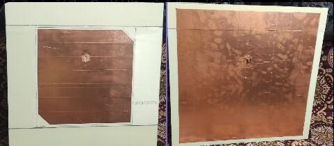
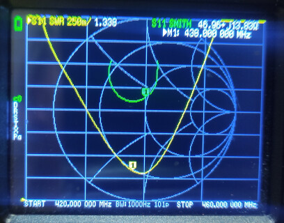
Recently I tried to make a RHCP patch antenna for 435-437 Mhz. A piece of foam and two layers of a copper tape with conductive adhesive. Patch itself - 310x310 with cut corners 40x40, reflector 450x450, foam - 500x500x20. Feed point 85 mm from upper side of the patch element. Weight - 191g.
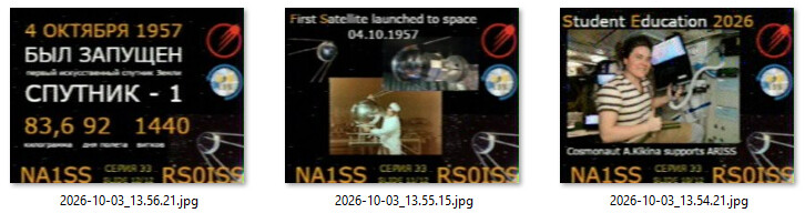
I didn’t collect much data about its performance but for now it might be equivalent to small Yagi (3-4 el.) or be slightly better than a turnstile antenna. Got some telemetry packets and pieces of digital pictures from UmKA-1 (rs40s) cubesat and some SSTV pictures from ongoing ISS event (not a big deal as ISS TX is 10W).
UmKA-1 digital image (partial) - it was stopped as, possibly, the operator saw that its telescope image was not stable and canceled TX but till that packet flow was stable without corrupted ones.)
Better idea - connect it to tinyGS to test its radiation pattern (visually on the map) as this patch antenna is more a directional than omnidirectional one and I don`t want to interrupt work of my Soniks (which was a satnogs one at first) ground station.
Mostly it is a 2 hours (really I’ve already had all the materials) joke project as it is quite big to grab it outdoors on a bike (possible but not so convenient as Yagi or my helical).
I haven`t find much info about modern cubesat reception on a patch antenna so i decided to find out everything by myself. But I think it might be (and is) used on a ground station with a rotator (more efficient). if you do not want for an antenna to stick on a 1-1.5 from your balcony and grab some additional attention from your neighbors patch might be a solution.
I’ll give this antenna a chance, but now I want to finish some of my other outdoor projects before it will be cold and snowy.
 Can anyone write a simple script for me please?