Satnogs - All Metal "Box Mountable" Rotator

Hi @azisi!

You got indeed the very first kit!
Others kits have just left all over the world and will help to improve it I hope.

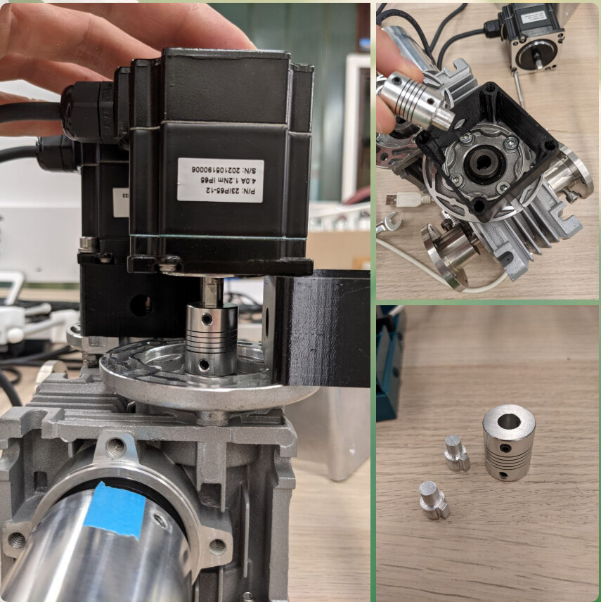
I thought a single cable tie would be enough to solve this problem I already had, but indeed it seems necessary to add a second one, or a notch in the 3D printed part to solve this problem.

If you are talking about the drivers being too hot, in my setup, the box with the drivers was outside and naturally ventilated, that’s maybe why I didn’t have this problem.

But these stepper motors are rated for 4.0Amp https://www.omc-stepperonline.com/download/23IP65-12.pdf.

What I noticed then was that the larger the microstepping, the lower the current required (for a given speed) and the lower the torque. For the most power and speed (and with drivers that support it) I think the ideal is therefore to have the least microstepping.

As for the cables, if they are really too hot it would be necessary to provide a larger section.

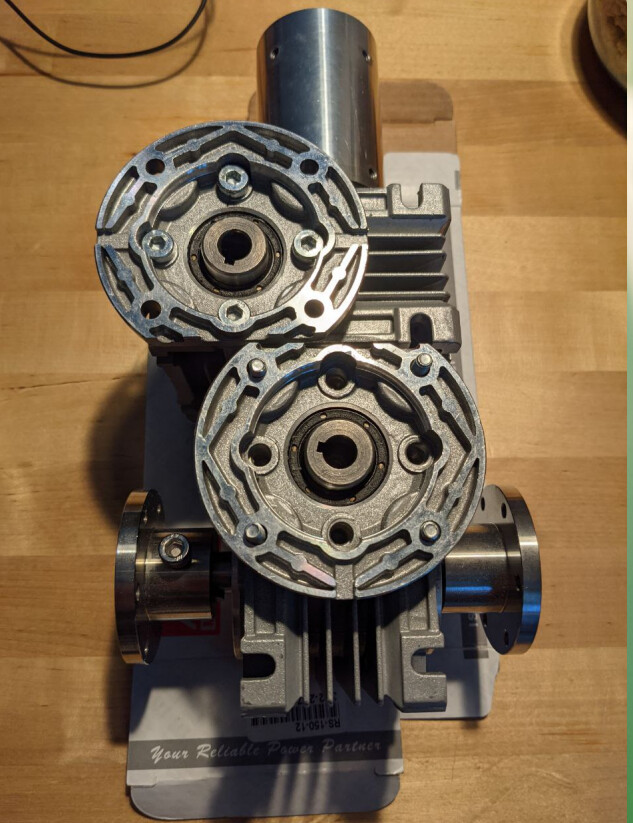
It seems to me like a very good idea, I need to take a look at it, but the rotator need no power when on idle because the reducer is not reversible.

Please note that the gear ratio is not 50 but 80 on your rotator, also I am not sure about this value of 0.4, it seems that it can vary depending on the manufacturer of the RV030. The best would be to conduct a torque test in conditions…!

That is a very good comment… I totally forgot to publish it!
It’s a very slightly modified version of the original code for the rotator controller, only the speed, acceleration, gear ratio, and pin are modified. I will quickly correct my mistake!

I think I definitely need a bit of help to understand how to write correctly something in the wiki, but yes with great pleasure!

Thank you very much for your feedback, which I hope will help to improve SuperAntennaz!

Yoyo

6 Likes

Hey @Yohan_Hadji! I confused with peak/RMS - rated current :slight_smile: . So the correct current configuration must be: RMS current 3.5A (4.9A peak). I will investigate more the over temperature issue with this setting.

Also do you know if this gear box has a setting to reduce backslash?

1 Like

Not that I am aware of, in fact there are several different backslash that you can separate

  • There is a first backslash between the end of the stepper motor axle, and the worm, so that the worm wheel can rotate a little bit while moving the worm forward or backward

  • There is a second (I think very small) clearance between the worm teeth and the wheel teeth

  • Finally there is another very small play between the wheel and the axle (with the axle key)

  • (And a last play normally inexistent between the axle and the key hub (which if it is well secured with it’s screw should not be able to exist at all))

But all this together, I had measured, was in the end only a play of ~ ±0.4°.

Nice!!
I mean that:

The play of both axis in this set up are bigger than ~ ±0.4°, so i need to investigate.

1 Like

To be sure you can check by removing the stepper and holding the part the stepper motor is rotating, this way you can isolate each play.

How do you measure the angle? (I had used an IMU)

Nice!

We will use a digital level-protractor.

Good evening @Yohan_Hadji and others, as I am new into this area the rotator with the RV30 worm reducer seems to be a perfect rotator for me. But with the first link to this 80:1 worm reducer to noted that there are some tolerances and that a NEMA23 stepping motor has other tolerances and does not perfectly fit to the worm drive. Do you have a link for a fitting motor and worm drive or did the actual available parts fit together without any problems ? I know that I will need some additional parts as a Shaft Sleeve Adaptor or a double output shaft but I think the most important parts should fit together. Thanks de Gerald, OE3GOD

1 Like

Hi Gerald!
Thanks for your interest,

Could you please give me a link of the reducer you think don’t have the right tolerances to be sure we are talking about the same part ?

All reducers I’ve been using were basic one, and were fitting perfectly with several different NEMA23 steppers motors.

Yohan

Good morning @Yohan_Hadji, sorry, I mixed the links for the worm gear and a cheaper flange you did not recommend.

I would like to buy this item:

Best Regards
Gerald

1 Like

Good morning @oe3god,

Indeed, the specific flange you give the link is a part which was used on older versions, it is not a part that I recommend now, and that is fully compatible with the new bracket, I advise you rather use this one (as specified normally on the parts list, but I’ll check anyway) :

However, for the gearbox, I can confirm that the one you sent me is compatible with a Nema 23

Fell free to ask if you have any other questions!

Yohan

1 Like

Hi All!

A first version of the instructions for the controller and the electronic part is available on the github here :

Any feedback is really appreciated, and if you find any mistake please feel free to report them!

Yohan

5 Likes

Hi All,

Very quick update today :

It’s done! Thanks to the advices of @azisi, SuperAntennaz now have a first version of it’s wiki page, all the next upgrades, as well as improvement’s proposals from the very new users, will be presented on this page :

Here is a link :

https://wiki.satnogs.org/SuperAntennaz

Here is also a way to find it from the main page :

Build a ground station → Rotator table → “SuperAntennaz”

Or Rotators - SatNOGS Wiki and then just click on “SuperAntennaz”

Yohan

8 Likes

Hi @Yohan_Hadji, I’ve been working on the rotator in the past days… I have ordered slightly different gearboxes from a local supplier. The difference was the motor flange was round, so I had to mill it down a bit to fit the design.

The gearbox also fits 9 mm shaft. The motor shaft is 8 mm. I was trying to solve this by printing some thin adaptor to fill the space. It kinda worked, but the shafts were not aligned well.
I got an idea to use flexible shaft couplers. I had to design & mill a small adaptor to fit in the gear’s shaft. I have 3d-printed “extension” flange to ofset the motor by 32 mm.

Now I have both motors mounted & running smooth. I am working on the endstops now. I’ve decided to use induction sensors as they can be weatherproof. I’ll be back with my progress soon. BTW how do you solve cable entanglement when the power fails during negative azimuth position?

A kind hint on the kit: I’d prefer a bit longer screws. Maybe my gearbox is a bit thicker, at least when compared to the CAD model.

Adam OM7AAK

2 Likes

Hi @adamk!

First of all thank you for your feedback and those nice pictures!

If you are ok with it, I would really like to add them to the instructions with a new chapter “in case you want to use a different gearbox”, do you have a link or a datasheet for the specific gearbox you have been using ?

On the gearbox I have used the input shaft was 8mm but the stepper output shaft was only 6.35mm, this is the reason this part is needed to connect the stepper to the gearbox.

Your solution seems very interesting to me for people having the same problem, and if you are also ok with it you could publish the .stl or .stp files and we could add them to the repo.

This is a great question : on my setup I didn’t enable negative azimuth rotation in the software, but I had enough cable length so that the rotator could at least make 2 full turns before having a problem. I agree it’s not a great solution. However, in +6 months of use, I never had a problem with it.

On the gearbox I’ve been working with, the length was just fine, but I recognize now it was a mistake to not add a small margin. Is it only about the screws connecting the plates to the gearboxes or on all screws ? Is it not perfect but OK or do you need a new set of screws ?

I’m looking forward to see how it works!

Yohan

2 Likes

I bought this gearbox. It is the said to be the same type (WGM030), but in reality it has thicker walls. Thus the screws need to be longer. Also the input shaft was different. I would use longer screws also for the key hubs. The rest I can’t say, as I am not using the optical endstops. Luckilly we have a quite good shop with screws here in Bratislava, but thanks for asking :wink:
I will gladly provide my files and pictures once the thing starts working.
Great to hear that yours is working well! I definitely want negative azimuth… My current plan for azimuth is using two sensors close to each other to create a kind of quadrature signal, that will be detected by MCU and stored in EEPROM. That way the MCU will know even after reset which way to search for the home position. I can’t wait till the plan meets the reality :slightly_smiling_face:

2 Likes

Hi Adam,

Now I think the gearbox you have found is maybe really a different model, yours is a WGM030, and the one I used is a NMRV030, maybe it’s just about the name of the manufacturer maybe there is more, I don’t know.

I will try to find a CAD for your gearbox, or try to design it to find all the differences.

This is very interesting! So would you also use it for continuous position feedback?

To me it looks like there is not just one manufacturer. Let me know if you need me to take some measurements.
I think I don’t need continuous position feedback. There would be just 2 pulses per revolution at home position. When entering the “negative azimuth” the controller would receive “negative pulse sequence” and remember this. If rebooted in negative azimuth, it would start turning positive direction. After it passes the sensors, it would start default homing sequence. Similarly we could enable a second turn in positive direction (over 360°), there would be a “positive pulse sequence”.

1 Like

Ok I get it, if the sensor read “A…B” it is entering positive azimuth, and if it read “B…A” it is entering negative azimuth. That’s very smart! It might even be possible to do it with optical sensors too… Please keep us updated!

@Yohan_Hadji

Hallo there! Found this project yesterday while I was looking for something similar.
The last post is from last year… is the group still active?
Did someone from Germany built the rotator?

Regards from Horhausen (Westerwald)

Hi @ucarvelli!

I’m still alive! However I started university in September and my time is now very limited. I can say that five people (Belgium, Finland, Greece, and Slovakia, but I don’t think Germany yet) have already started building their own rotators, some of them are on this thread.

I had 3~4 requests for machined parts kits these lasts months, unfortunately, I don’t really know if I will be able to find the time to machine parts again and prepare packages.

However, I will always try to be here to help you in the assembly / use of your rotator. Let me know if you already have any questions about this.

Best