V3 coming soon !
7 Likes
Hey! Nice design!!
I have some questions to understand better the design:
- Do you put it inside a box like the previous version?
- Where does the bearing of worm gear is mounting (the side with the pulley)?
- How do you mount the mast for antennas?
- Do you have any provision to put encoders for position feedback in the output (i can help you!!)?
- If the design uses an aluminum box and somebody doesn’t find the same size, do you have any provision to put the mechanism in a different size box?
3 Likes
Hi @azisi
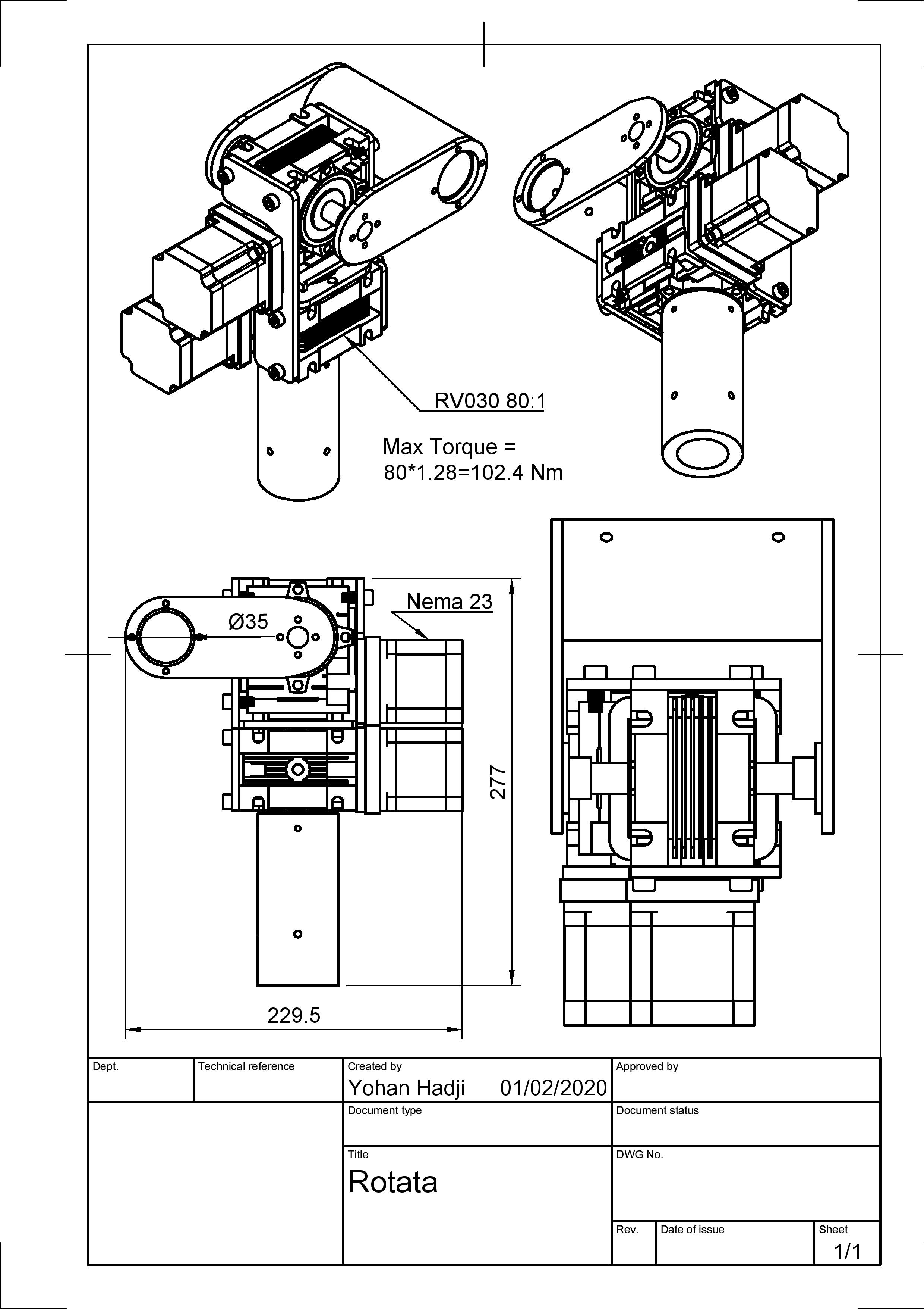
Yep for this time the design is made to be put in a box (Hammond 1550 H i think) but in the same time i’m working on another one which work with a special box :
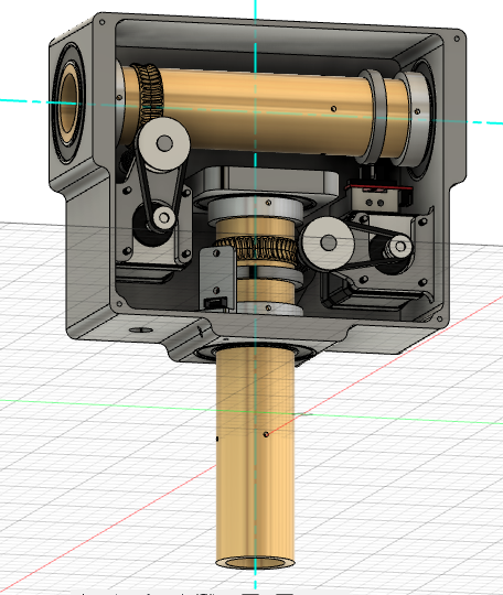
On the “market box” version, the block bearing is mounted on this part 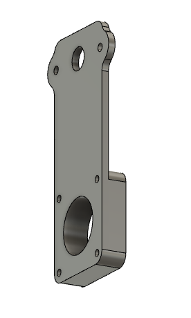
Which make the connection between the stepper and the worm rod
For the mast and for the antennas,
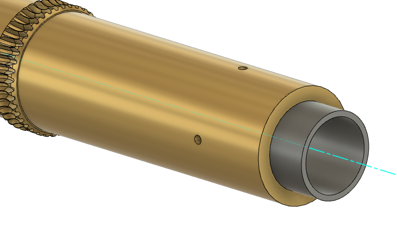
The rod (in black) is fixed by 4 screw to the worm gear/axis (brass color)
I would really like tu put encoders, i didn’t had the time to think to them, for this time i just added optical endstop in my design, but, yeah i could need some help to know how to use them !
About this different box size :
The mechanism is in 4 parts
1/ Axis/worm gear + Ball bearing for elevation
2/ Stepper + Timing pulley + Worm rod, (which is mounted in only one “solid” block
And the same for the azimuth
So basically you can mount it a bit as you want (for an example you could just mount it on a plate), the only limit is the length of the axis/worm gear (which is the same parts)
If it could help, it looks like that once mounted in a box

6 Likes
Hey!!
Seems that has some points which are difficult in fabrication like the motor mounts (i think that are embedded in box). Also for azimuth axis, it is better to use a thrust bearing instead of ball bearing( the top bearing). The mount of azimuth ball bearing (the one inside the box) it needs more support because takes all the weight of rotator and antennas. Also, you could consider to use bushings or plain bearings instead of ball bearing (for 3 ball bearing that are mounting in sides of box), because in this application the rotation speeds are low and the bushings or plain bearing could handle heavy weights.
The pulleys for timing belt are going to high maybe this is a problem for tension of timing belt and the stepper motor must have a long axis. Why are you using so big ratio for timing belt transmission? Which is the ratio of worm gear box?
I think that you need a more powerful mounting system either like Yaesu G5500 or SPID rotator.
I like a lot the idea with the different size of boxes. Have you estimate the cost of
the axis with embedded worm wheel?
I seems that in non-custom box design it exist space to put encoders for position feedback.
Nice design!! Keep going!!! ![]()
4 Likes
Hi @azisi thats really cool because maybe you dont wanted to but you really give me the answers to question that i was asking to myself !
Yeah i thought it would be a big problem, but the design was only a poc for me so anyway I should design it in 2 parts
I was also considering this 2 things (i just need design them now ![]()
I’m not pretty sure that i’ve well understand what you mean, are you thinking that the tension is going to be too high or ?
I’m considering 2 options the first is 16:40 and the seconde one is 16:60 (one the first image this is 16:40 and one the second one this is 16:60) I’ve juste wanted to have the biggest ratio as possible in the smallest space
Did you well understood that the 4 screw are through the 2 tubes ? I was thinking this was the most powerful mounting possible, but if you say that U bolt is better I believe you !
28$ / pcs for 2 pcs — 24$ / pcs for 10pcs — and 14$ pcs for 100pcs (price given by this instant quote system)
Thanks for your ideas and your help !
4 Likes
Hey!
Think about the torque that produced from the tension of belt and how wear the bearings of stepper motor. Also how easy you can find a source for stepper motor with big axis.
Also, you need to consider about the rotation speed, take a look here ( Mechanical Analysis [WIP])
No i didn’t understand ![]() , but due to antennas load the holes would be open more (the brass axis with gear).
, but due to antennas load the holes would be open more (the brass axis with gear).
So you are using standard tooth profile and module for gear box, because if not use you have additional cost due to custom tooling for machining.
![]()
4 Likes
Hi All,
After weeks of reflection, I must assume that my design isn’t the good one.
The design was successfully working with a tiny antenna. But with this antenna the result of the station wasn’t better than with a omni antenna and without the rotator, so not really usefull…
Then i bought a very good antenna, which was as beautiful as it is heavy, and and right away all the problems happened, and nothing was reliable anymore.
So what is the best solution ?
Spenting a lot of time to build a rotator for A to Z which can only carry a small antenna ? I don’t think so, it was a very interessant work ! but this isn’t the good solution…
For this reason, this project, in this first iteration come to an end, but something else is coming ;
I definitely needed something more reliable, but I still didn’t want to buy a commercial rotator, I really wanted to keep the spirit of construction. Inspired by everything that has already been done (SPX-02 for exemple) and what works really well, SuperAntennaz was born.
The main part is this one : Réducteur de vitesse de moteur à vis sans fin, sortie 14mm 5:1 80:1, NEMA 23, DC, RV030 | AliExpress
The number of parts is really small, there are just 3 aluminium plates, and two adapters to fix the rotator on the masts.
I know that the first(s) objectives of my project aren’t respected anymore, but if this design interest you too, just let me know, and i will continue to put update on that thread !
Yoyo

8 Likes
Still interested! Please keep sharing your progress.
2 Likes
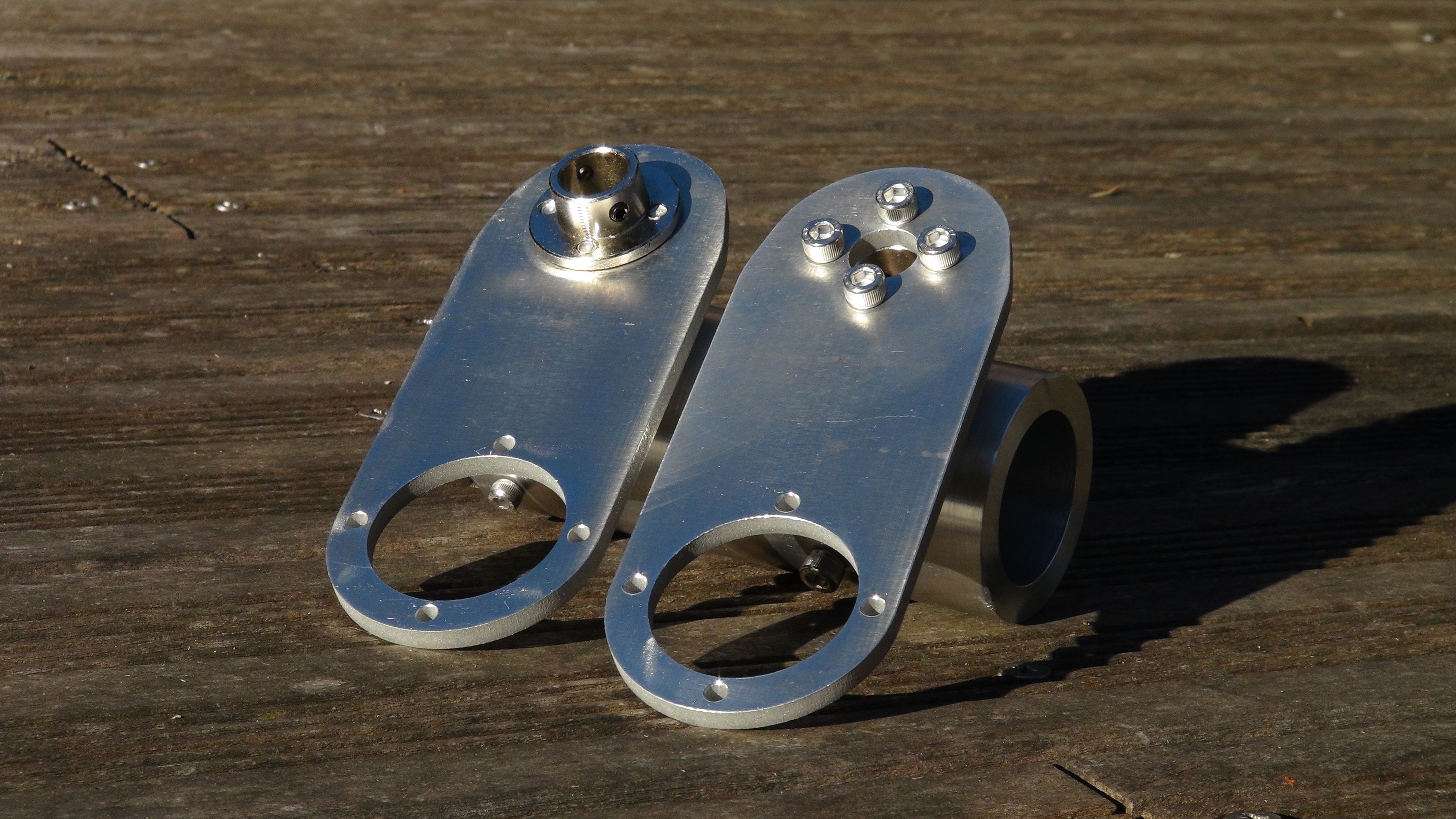
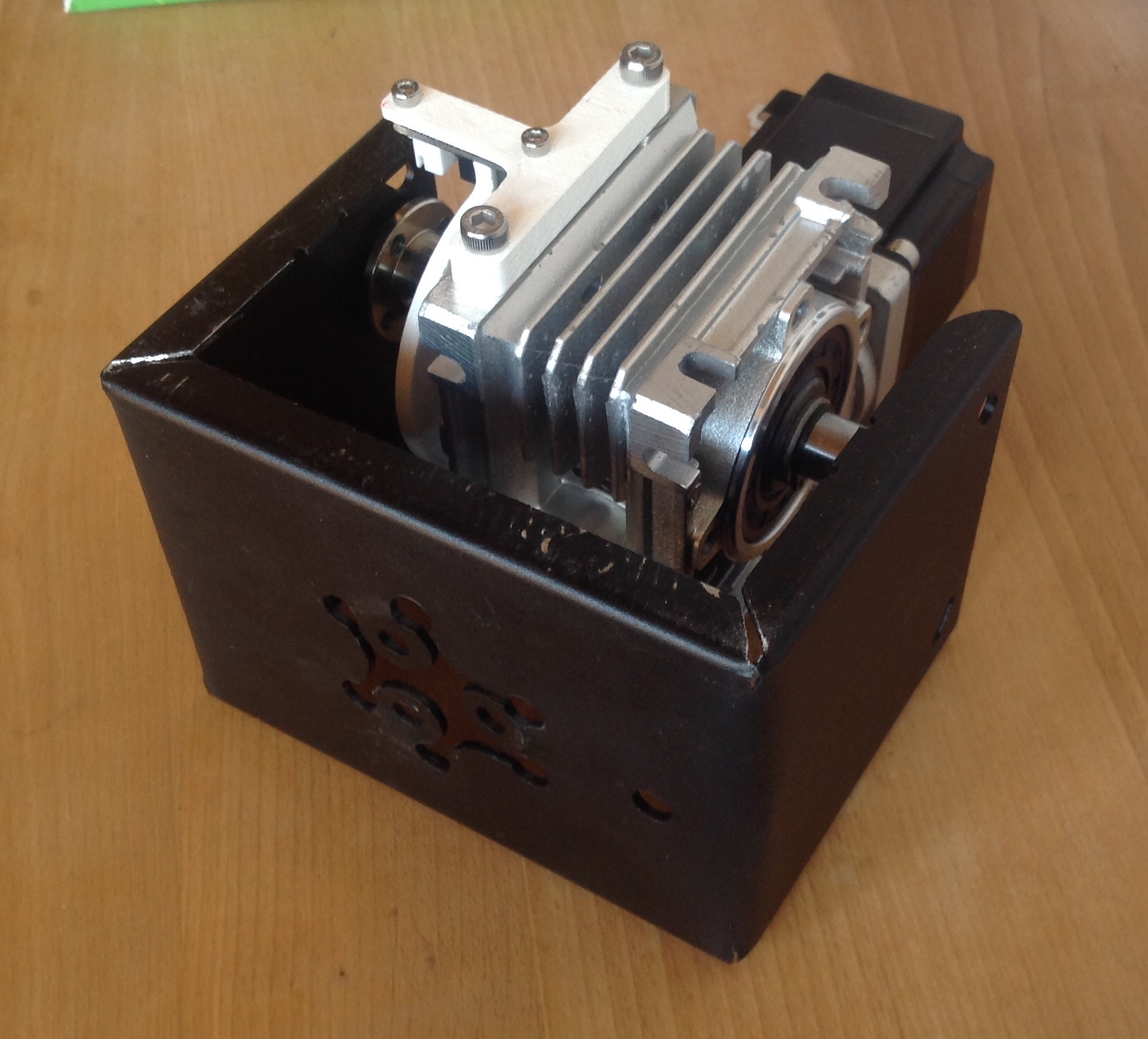
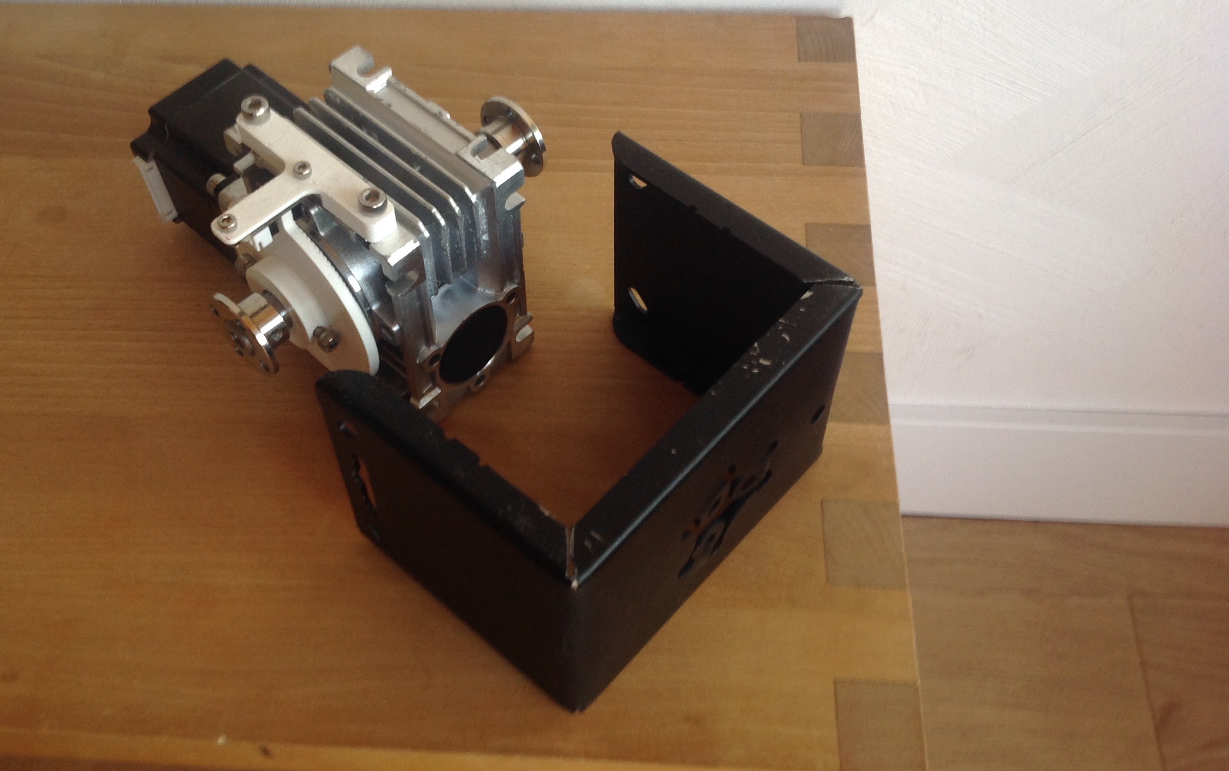
Work in progress !
For 80$ I’ve get this parts machined
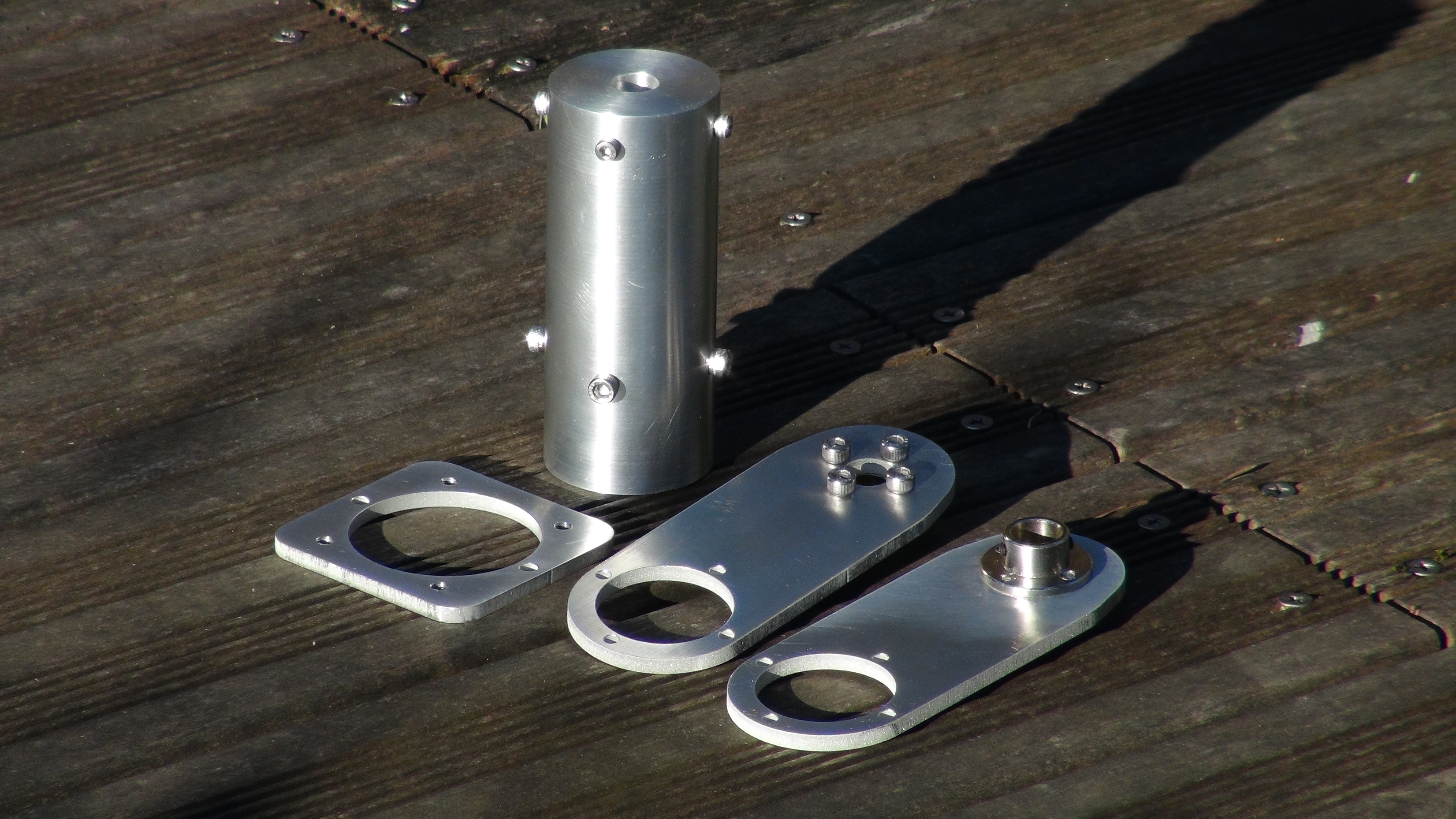
The first one is for the connection between the azm motor axis (https://fr.aliexpress.com/item/4000378786811.html?spm=a2g0s.9042311.0.0.64a86c37QtZruy) and the 35mm Aluminium Mast
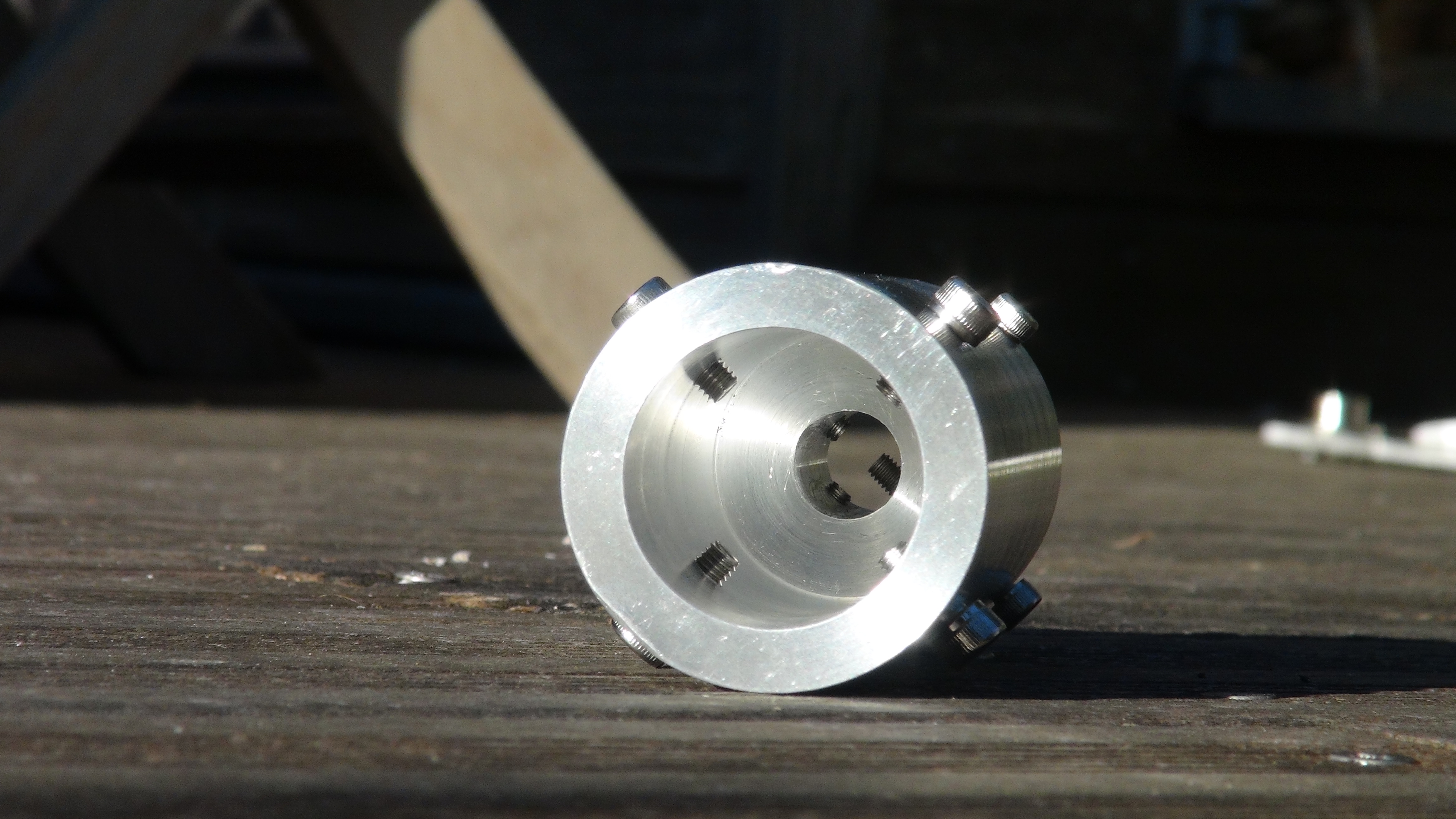
-The second one is for the connection between the two Reducer (RV030 Réducteur de vitesse de moteur à vis sans fin DC, RV030, sortie 14mm 5:1 80:1, pour moteur NEMA 23 | AliExpress)
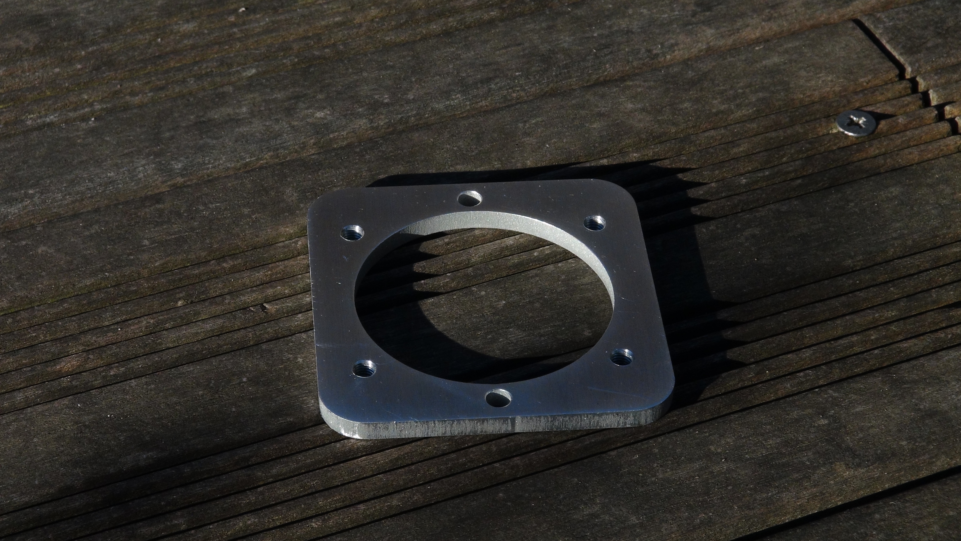
-And the lasts one are the connections parts between the “double” elv motor axis (https://fr.aliexpress.com/item/4000378899246.html?spm=a2g0s.9042311.0.0.64a86c37QtZruy), the parts is done two time, one for the left side and one for the right side, and finally we fix this flange on the plate Bride en acier galvanisé, 3 14mm, haute dureté, couplage d'arbre, bride rigide, couplage, Guide moteur, roulement d'arbre | AliExpress
I am now waiting for the aliexpress delivery of the last elements to start the assembly…
5 Likes
So two RV030, Two NEMA23, and a couple of parts to attach to antenna? Pretty slick!
What gear ratio are you looking at on the RV030? (ans: 80:1 in comments above)
What watts/amps on the NEMA 23?
What are you thinking for the software driver?
1 Like
Hi @KE0PLO,
Indeed, that’s the purpose of making it very simple 
I use 2.8A NEMA23 stepper motors (56mm and 1.26Nm),
For the first test I will use a 12v 100W (34W for 1 Stepper) power supply, and stepper drivers which can cary up to 4.0A peak, and 9 to 42 VDC.
I’m now waiting for the last part from aliexpress…
For the soft I will still use Satnogs with a Raspy and an Arduino, but nothing stops me from removing the raspberry and connecting directly to a pc to use GRpredict.
Thanks for you interest !
2 Likes
Bravo ! Superbes résultats ! Great job ! I’m very impressed ! 73’s Martin 9V1RM / F8UKP
2 Likes
Thx Martin !
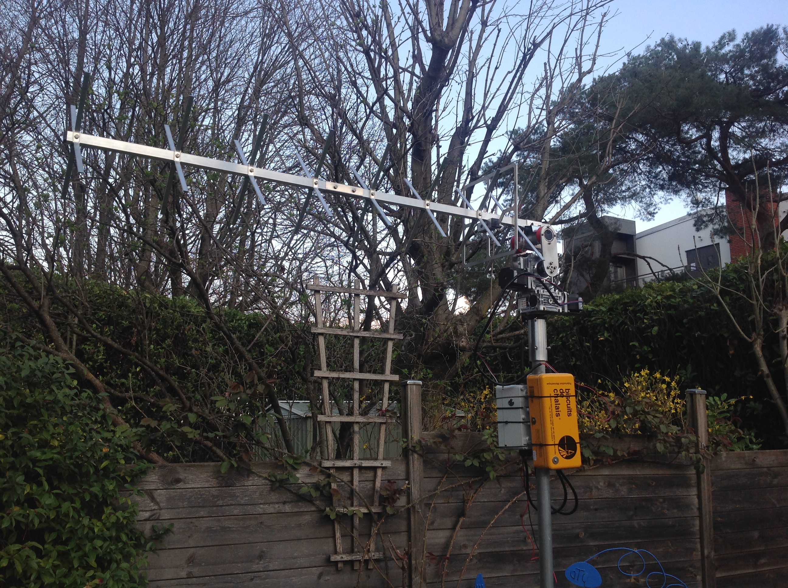
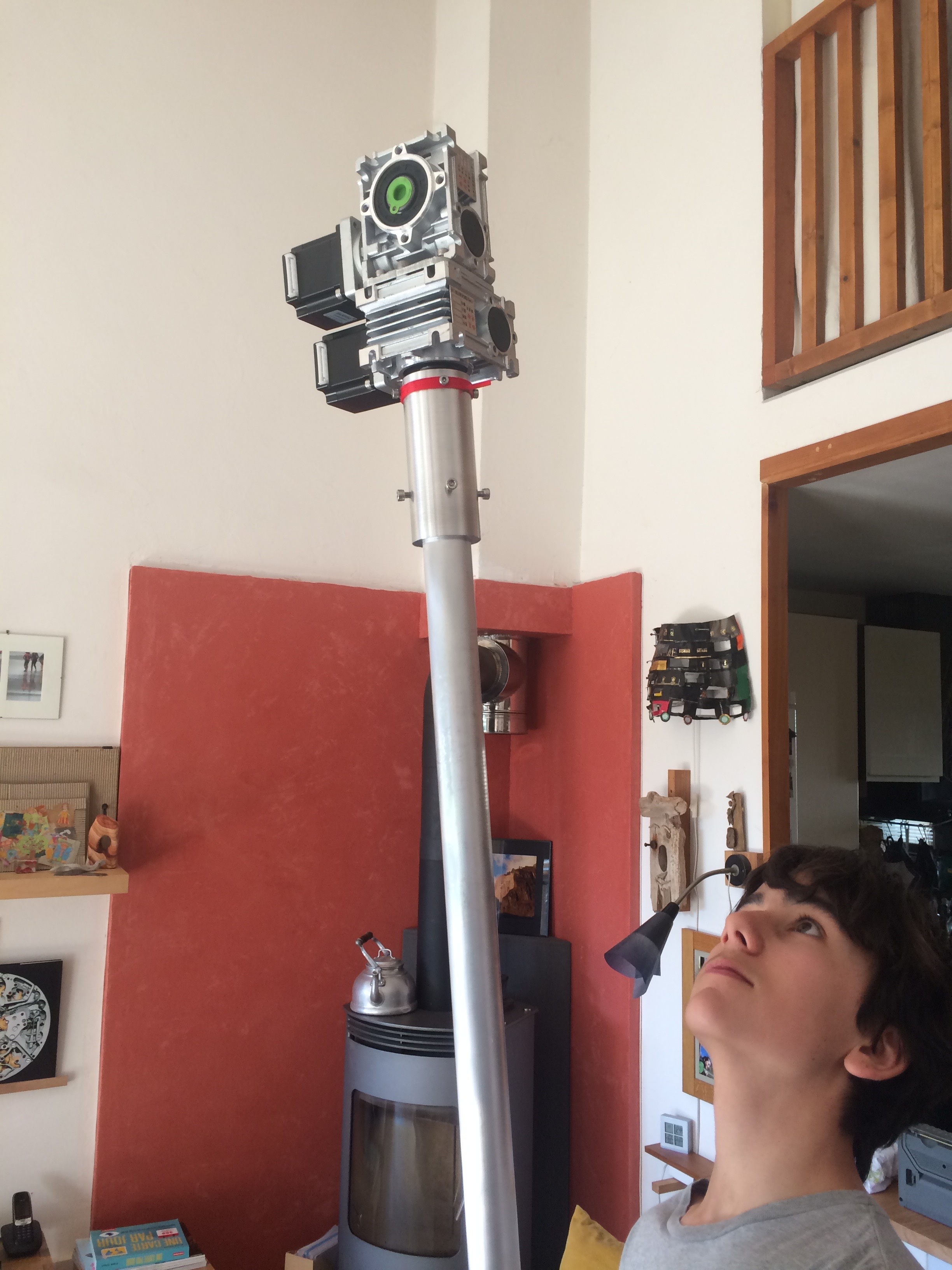
Some better pictures…
And to see it in action : SuperAntennaz - Rotator - Operating Version (Spring 2020) - YouTube
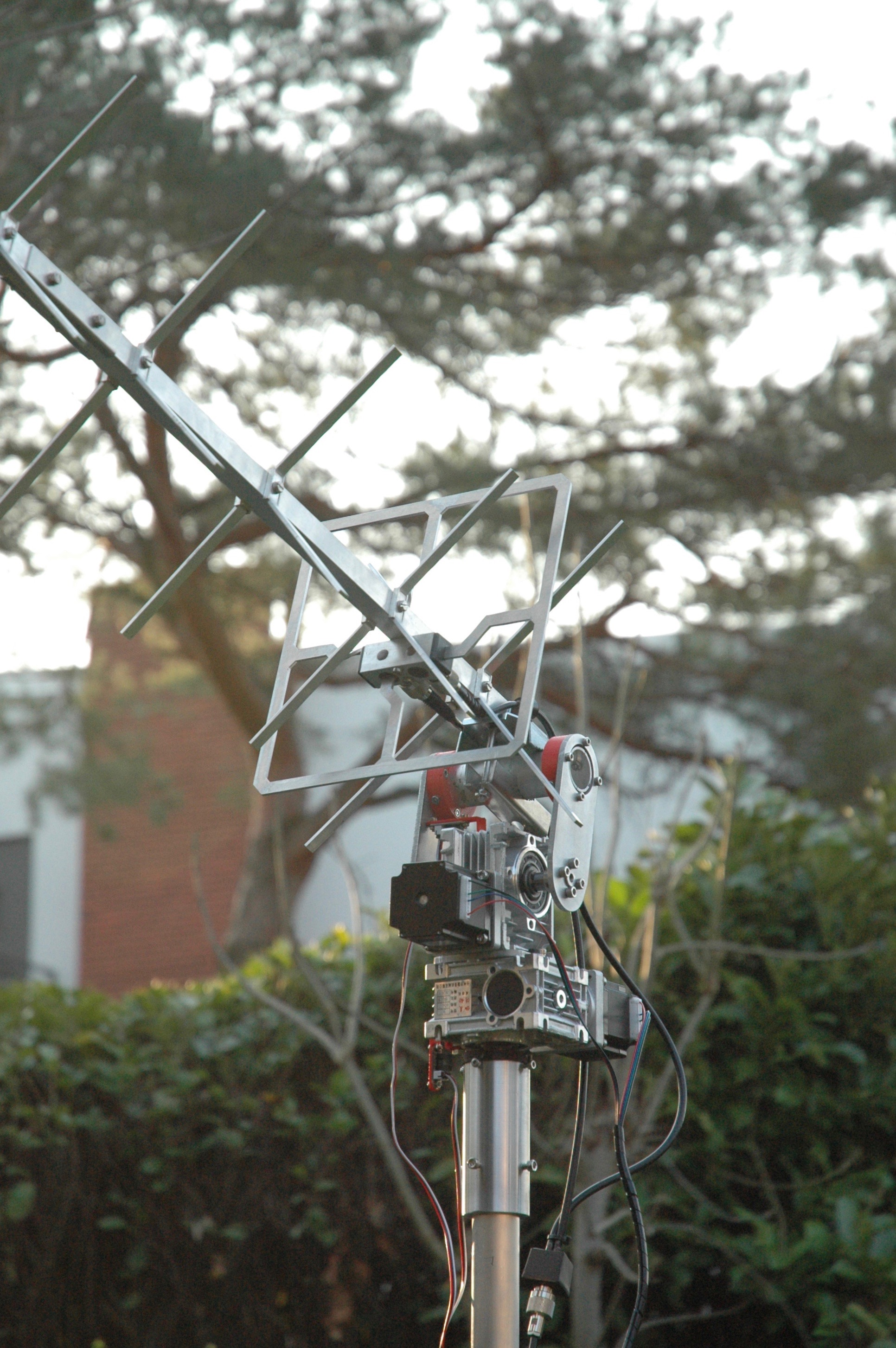
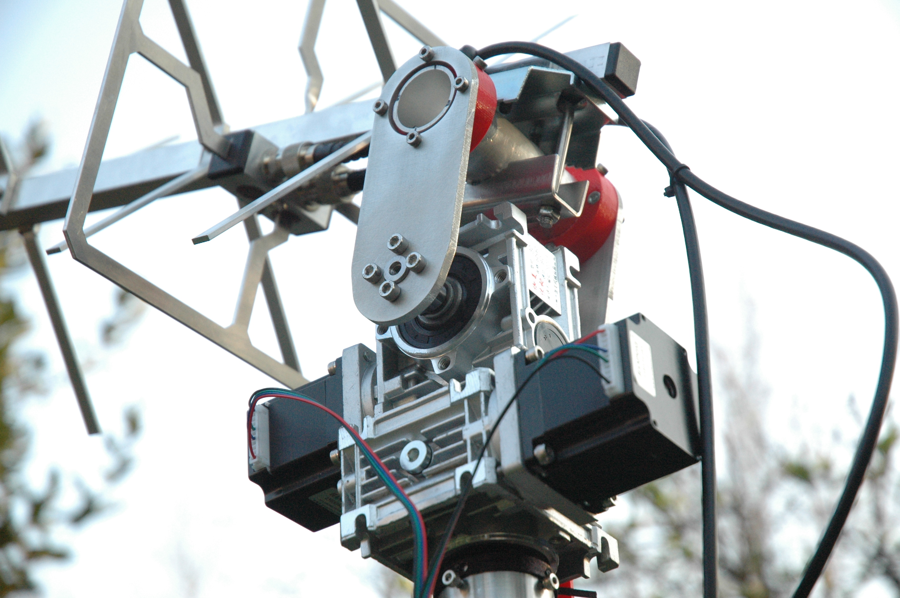
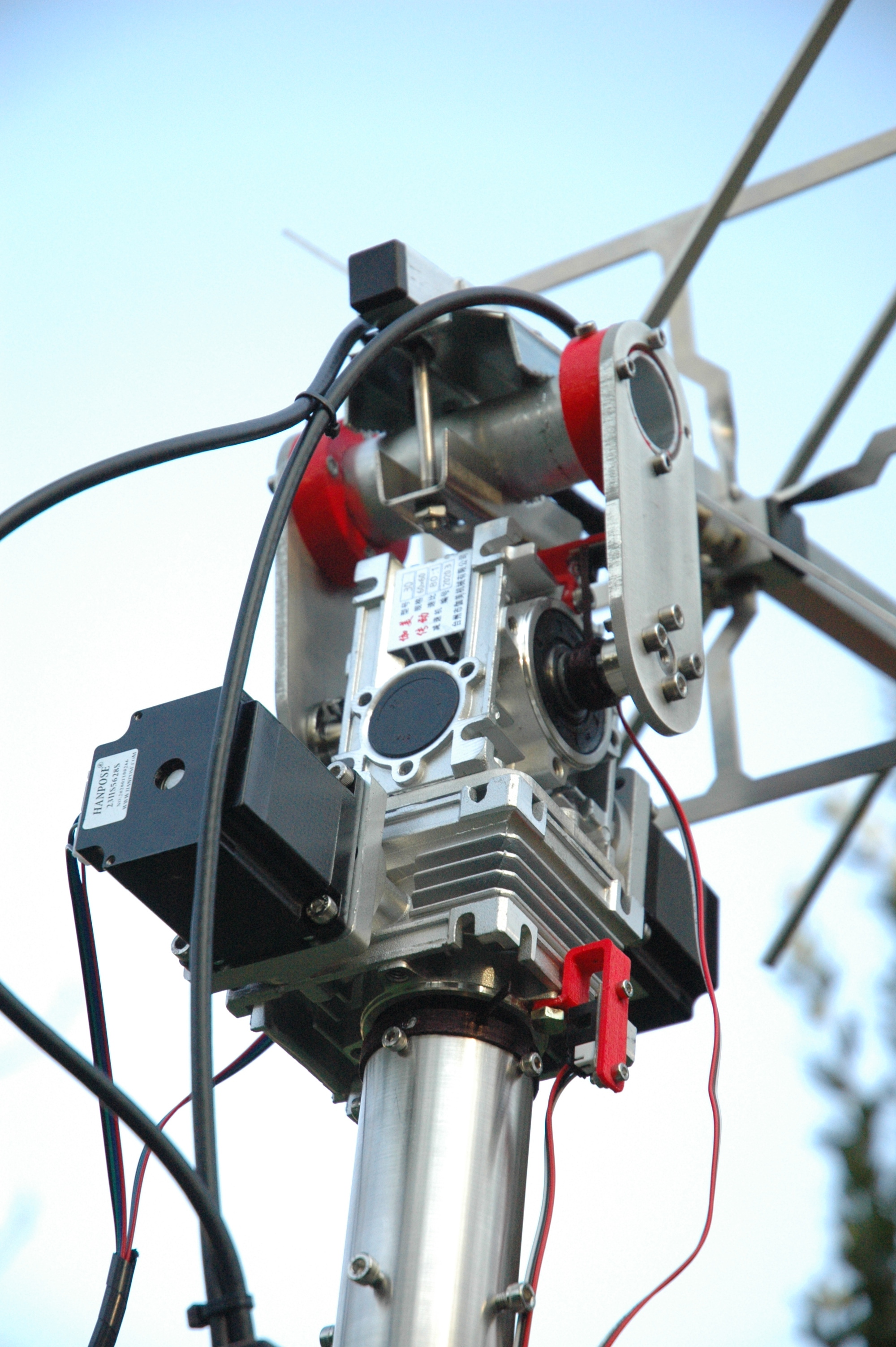
9 Likes
After few days “on” mechanically everything works, which is good, but I now have other problems with the signal reception but anyway.
So what’s next ?
Three things can be improved :
-
I would like to test something different for the bracket, which would simplify the assembly-disassembly and make it more reliable, with a laser cut and bent plate, which costs about the same price as the old bracket, or even a little cheaper.
And then on this bracket we will mount that type of jaw : Bride pour tube Ø 40mm
-
The Optical Endstop are as precise than shit in day light, so there are 2 solutions, the first, (the one I’m actually working on) is to change a bit the design, to stop daylight switching off the endstop when he need to be switched on. And the second possibility is to finally switch to encoder, which will offer the possibility to use DC motor too.
-
To facilitate the build, I’ve done a small come back on the way reducer are mounted together, there was only one horizontal plate between them, which will be replaced by two vertical plates
A Few people contacted me to ask how they can build their own Rotator. What I purpose to everyone who want to build it is to speak about the project to people who may be interested as you. I will create soon a registering list so that then as 5 or 10 people are registered we can make a grouped order for machined parts, which can reduce part costs from x2 to x10. I may then create a kit with all the machined parts, the screws, and build advices, if you want
One more time feel free to ask me any question you may have !
10 Likes
So happy to see your progress! My worm gears have arrived, waiting on stepper motors. Following in your footsteps.
2 Likes
2 Likes
@Yohan_Hadji Love your work! You inspired me to build your setup.
A few questions …
Have you noticed the highly universal antenna tracker from K3NG?
This tracker offers the possibility to connect different sensors.
Do you know how that part of the SPX02 works? What kind of sensors do they use?
How do you plan to implement the azimuth / elevation angle feedback?
Any progress with the DC motor?
1 Like
Hi Rene,
Thx for the link, it seems to be a rather interesting project, I had started to do my own research on the different possibilities, without finding anything very interesting.
In fact, I’m not sure how much work it take to build a good controller once you have a rotator, you just have to find the right box, the right badass connectors, and adapt the whole thing. But it’s like for the rotator and it took me 10 months 
In the system of my dream, the idea is to have the Rotator, which would have only 1 cable that goes to the controller, with at the output of this cable 2 connectors, which are connected to a pcb that makes the interface with the motor and the sensor.
Then in this controller there would be the power supply, the drivers, and the Arduino.
On this controller, would be connected in USB or in wireless USB the box of the “Computer” with the raspberry inside, but the controller should be able in principle to work with any computer with GRpredict on it.
We could of course add a color LCD on this box to display the station’s monitor.
I don’t know how far the wireless USB jacks work, but I’d find it really cool to have the Raspberry with the station monitor on my desk.
If I’m not mistaken, the SPX-02 uses rotary encoders, they use brushed motors so they don’t have many other solutions. They have a resolution of 0.5° on the 800€ model and 0.2° on the 1100€ one.
Afterwards there can be resolution in 2 ways, for example if I consider that I never skip steps, the reducer is 80:1 and I use 4 microsteps, for basic steps of 1.8°.
So 1.8/4 = 0.45° / 80 = 0.005625°, So in theory stepper motors will always be much more accurate than any encoder, as long as you consider that you don’t skip any steps.
It might be smart to think about modifying the code, to use the stepper accuracy most of the time, and every 5 minutes, do a syncronization with the encoders, to catch up the lost steps.
So far with the stepper it works well with just an optical endstop for the start up. But in 2 clicks the design can be modified to replace this one by an encoder.
Finally this is what came out of my research for a brushed motor
Nothing crazy, and it’s even much more expensive for the motor (than with a 10$ Nema23 stepper motor), But it’s maybe a little cheaper for the Driver.
I also continued my research to improve my bracket, I wanted to order a Machining / Bending to test the file, but finally I didn’t have the budget so I recycled an old steel plate that I cut and bend by hand to make the “U”. The plate is a bit too large but it’s fine to test the margin and the lateral/vertical strength and find the weak point of the design
Just as a reminder this replace the old over designed bracket design 
3 Likes
@Yohan_Hadji
Hi Yohan,
Thanks for your detailed answer with links and photos.
I really appreciate it!
Any progress with your project?
It is also my dream not to have cables between inside and outside. Want to be able to control everything remotely. I think that is possible.
All electronics in a waterproof box with only a WiFi connection for the data. Something to figure out after the mechanical part.
The past week I have been busy with further researching stepper motors and everything related to it. Especially since certain things, such as the required torque and which drivers / controllers were needed, were not yet clear to me.
Most of it is now clear to me.
I am going to order the following items to experiment with. Gearboxes, Shafts, Nema 23 1.8Nm 3A motors and TB6600 drivers suitable for 3.5A / max 40V motors.
I think the original Raspberry board is under-dimensioned with 2A, hence this switch. Do you experience torque problems?
My intention is to control a mesh dish of 2 meters in diameter with a UHF and VHF antenna on the left and right. Obviously well balanced.
I don’t know yet whether the TB6600 is easy to connect.
About the gearbox / motor. I have no idea how to mount the end plugs yet. Did you make the sensor holders with a 3D printer?
I see in your photos a white ring but also a curved, metal orange holder. Are those sensor clamps? Have you designed these yourself or are they from the V3 project?
The Arduino is already equipped with the right software. Still have to figure out how to connect it to the raspberry that the SatNOGS software runs on.
For me, the most difficult part of the project, apart from the gearbox, is the mechanical part. Mast holder, bracket, end stops … I have to have everything made elsewhere because I don’t have a mechanical workshop.
Last question … What is the reason that you want to continue with DC motors?
What do you experience as a disadvantage of the stepper motors? Lack of torque?
Does everything remain synchronized, even after 25 turns?
After this post I also upload some inspiration photos, first figure out how that works