Rotator and rotator controller shopping list

Hi all,

I’m very new to all of this. I’m looking to build the SatNOGS rotator V3 and the rotator controller to start my ground station off. However I’m very confused. I only just figured out after doing some digging that you have to get a custom PCB printed for the rotator controller. There also doesn’t seem to be a complete list of parts for the electronics of the rotator. I have so many questions, so I’m just going to number them and hope one of you kind folks can help me out in my quest to ready up for my build!

  1. Is V2 the latest version of the rotator controller? If so are clones of the discontinued Arduino Pro mini acceptable for use in place of the original?
  2. Is there a list of all the individual bits I need to put the rotator controller together?
  3. Is there a comprehensive step by step guide for assembly?
  4. What motors do you use for the rotator?
  5. Is there a more detailed guide on rotator assembly than the one that is available on the wiki?
  6. Is there a universally accepted comprehensive required item list for the rotator?
  7. Is there any detailed information on the power supply of the rotator controller? If so where can I find it? (There’s nothing substantial on the wiki).
  8. If all of these questions have been answered a million times and you are sick of hearing them, could you point me in the direction of the answers please? I’m keen to help myself as much as much as possible in addition to getting help from others.

Sorry for asking so many questions and thank you for your time. I just need someone to hold my hand for a bit until I find my feet and can start giving back to the community!

Look forward to hearing from you all,

Lorcan.
Hi @lk151 – welcome from another newbie! I’m juuuust starting the process of building out a ground station myself, so I’ve been trying to collect this kind of info too. I don’t have all the answers, but hopefully this will be somewhat useful.

I believe so; I don’t see a later tag or git branch on the repo.

No idea, I’m afraid; perhaps someone else can chime in here.

Is the bill of materials what you’re after? Also, it looks like you should be able to get Oshpark to print out the PCB boards.

You can find assembly instructions for v3 of the rotator on the Ohai site. (Side note: hardware assembly instructions are being migrated from the old Dozuki site to the new Ohai site. This is a work in progress. I don’t think I see anything on the old site that’s relevant to your questions, but you should double-check that. :slight_smile:) I also came across this set of notes from someone who has assembled v3, which may be of some use.

The wiki mentions both steppers and DC motors; electronics isn’t my strong suit, so I’m not sure of the tradeoffs, but this post goes into the details a bit. You may want to check in the gallery section of this site, or a search through this site for “motors”.

Mechanical assembly of the v3 rotator can be found on the Ohai site. There’s also a fun assembly timelapse video on YouTube, though I’m not sure how useful it will be to you. :slight_smile:

Is the bill of materials on the repo what you’re after? As for sourcing, this post has a good list of places to buy parts if you’re in the US or Canada.

The only mention I can find is this post, which mentions the v1 branch of the satnogs-rotator-controller repo…but AFAICT, the v1 branch was merged in a couple years ago. I haven’t dug around in that repo yet, so possibly power suppy files are in there…maybe someone else can chime in.

Speaking for myself, I haven’t seen all these questions before, and I’m grateful you asked them…like I said, I’m early in the process of building a ground station. (For no particular reason, I started with the antenna…so I haven’t started to dig into the rotator yet.) I’ve tried to improve the wiki, which is meant to be the one place that holds this info, or pointers to it…it’d be great if you could have a look and add anything that’s missing.

Hope that helps, and definitely keep us posted on your progress!

Believe the power supply is built into the new v2 controller board.

I’m in the process of building a v3.1 myself and had to modify some of the parts/prints to fit imperial/USA components (for the pvc pipe). Haven’t started assembly yet so don’t know how things will line up.

Also those mechanical instructions are for v2/v3, not v3.1

I started out printing parts for 3.0.1 which is based on old design and realized there’s a 3.1 version out however documentation seems scarce along with documentation for the v2 controller and the 3.1 rotator.

V2 controller info found here:
https://wiki.satnogs.org/SatNOGS_Rotator_Controller

First off thank you Saintaardvark, that’s answered pretty much all my questions. Also thanks ka4jwb for the info on the controller board.

It seems the deeper I dig into this the more questions I come up with. I’m hoping you guys can continue to help me out.

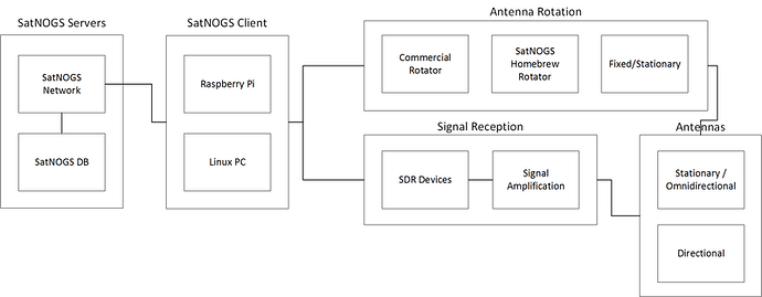
  1. As per the block diagram for the ground station, I need some clarification. Is the signal amplification done on the Realtek SDR? Is it done on the controller board? Where does the arduino on the controller board connect to the Raspberry Pi with the client on it?

  2. I don’t quite understand the .csv files for the rotator controller and encoder. Would it be possible to explain the way the information is laid out? I don’t understand the terminology specifically in the 2nd column.

  3. What is the stock Realtek SDR like in use with this ground station? If I sub in a HackRFOne, is it compatible and if so is it a worthwhile trade? What do I gain for a hardware piece multiple times the price?

  4. What is the role of the encoder? I was under the impression that the encoder was necessary for signal transmission. I was also under the impression that the ground station design at present was only capable of receiving signals? Is this the case? If the system can transmit signals, don’t you need a ham radio license?

  5. Is there a detailed guide in how to put together the controller board? I.e where to solder all the components? Also where to get them all from like the BOM for the mechanical and electrical breakdown?

Just want to thank you all for your patience. I know these seem like dumb questions but I’m not an electrical engineer, I’m an aerospace student. I want to make this more accessible and easier to understand so that people like me with average electrical knowledge can come in and build one of these. I’m also under an enormous amount of pressure from my supervisor to understand all elements of this ground station so I can get a plan together to build one.

I plan to produce an in depth assembly guide for the mechanical parts of the rotator as well as anything else I manage to build in the timeframe I have for this project. I’ll post it here and attempt to better the wiki using it when it is finished.

The hand holding shouldn’t last much longer!

Thanks again for your time,

Lorcan.

Also, 6th question here;

In the BOM for the electrical components, it states a 50:1 DC motor in addition to the 2 stepper motors. Is this optional? I.e DC vs. stepper or is this mandatory in addition to the 2 NEMA17 motors. What is it for?

Thanks again,

Lorcan.

Hey @lk151 ! Answers inline:

Amplification is generally done by a LNA (low noise amplifier). There are multiple options there like:

  • A wide-band LNA next to your SDR (see LNA4ALL and similar)
  • A band specific (or two) pre-amplifiers next to your antennas (see here)
  • No amplification at all… just pump the gain of your SDR (not recommended for rtl-sdr)

Which .csv files are you referring to? Can you link to them?

As long as your rtl-sdr is one of the modified latest generation ones you should be good (nooelec smartsdr, rtl-sdr.com v3 etc). Most stations on our network use those. Interestingly HackRFOne is not an improvement compared to those rtlsdrs. We have tested it before (and we support it on software) but proved to be quite deaf. Higher end SDRs are of course better (USRPs etc).

Where did you see a reference on encoder? SatNOGS client, actually supports both TX and RX (of course given that your SDR can transmit). The vast majority of the stations are operating RX only, and indeed you need a license to do TX so we are pretty careful about it. Worry not though, your station will not be TX-ing anything unless you specifically instruct it to do so (you can check the UPSat parts of the satnogs-client code for that).

This (together with the controller software) is the missing piece of our rotator design. It has been done and tested, but not documented. @azisi can provide ETA and details on that.[quote=“lk151, post:4, topic:1369”]
I plan to produce an in depth assembly guide for the mechanical parts of the rotator as well as anything else I manage to build in the timeframe I have for this project. I’ll post it here and attempt to better the wiki using it when it is finished.
[/quote]

@saintaardvark has done a phenomenal work on improving the documentation lately. You should probably coordinate on that so we can make everything better for newcomers!

It is an OR situation. BOM has both, but you need to select one of them as options :slight_smile:

Thanks for your patience and sticking around :slight_smile:

Thanks for getting back to me @pierros.

I’m assembling a list of things to add to the documentation for the ground station while building my project. So I need to be sure of a few things.

So the LNA is not included in the electrical BOM that I can see. Is it in the antenna BOM or has it been omitted? Which of those pre-amps would work/are good? Many of them are very expensive. I’m going to look at what you can swap and change or introduce in this design and make an accessible document on it so absolute beginners can understand it. Right now it seems it’s modular but only if you know absolutely what you’re doing.

The files I’m referring to are the .csv files for the encoder located here:
encoder_as5601.csv
https://github.com/satnogs/satnogs-rotator-controller/blob/master/satnogs_encoder/encoder_as5601/encoder_as5601.csv.

and

satnogs_controller.csv
https://github.com/satnogs/satnogs-rotator-controller/blob/master/satnogs_controller/satnogs_controller.csv.

I’ve delineated the files and shoved them into excel but the second column doesn’t make any sense to me.

I would love to know the parameters and results of those tests. I’d like to document them and share them in another accessible doc.

The encoder I referenced is the one in the rotator controller files on Github. In terms of the TX support, are there any supported SDR’s that allow for transmission? This is all stuff I want to document and share.

When you say the controller software is missing, I’m a bit confused. How does the ground station function without the software? Does the software control the tracking of the ground station?

I’ll be sure to do my best.

One of the things that I was unsure about was which was better in terms of stepper vs dc motors. Is this documented anywhere?

Thanks,

Lorcan.

Hey @lk151 – +1 for an easily understood intro for beginners…I’ve been wanting to add one to the wiki for a while now, particularly something that outlined the different choices that could be made (which radio, rotator vs no-rotator, etc). I’d encourage you to feel free to post to the wiki; we can all work on it there to improve it if needed. Feel free to ping me here if there’s anything I can help with, and good luck!

The as5601 is a dc motor encoder. If you’re going the stepper route it’s not needed

Not certain, but I think that @pierros is referring to the Arduino firmware for the rotator.

Exactly! This is still WIP

If this is the case, are all of the ground stations on the network omni-directional stationary antennas? Have people actually got signal reception from satellites using the rotator and the software to control it?[quote=“ka4jwb, post:9, topic:1369, full:true”]
The as5601 is a dc motor encoder. If you’re going the stepper route it’s not needed
[/quote]

This is useful to know thanks very much.

Hi,

I’m also trying to assemble the v2 controller board stepper version (I already have sourced all the components and PCB’s, hope to have it finished in the following weeks.).

Is it correct to assume that the software in the gitlab repo is suitable for the v2 board? or it is for the previous one?

Thank you.

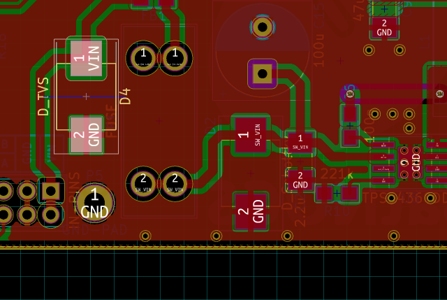
Have you gotten around to soldering the PCB yet? I’m stuck on one piece. On the BoM there’s a D4 diode part # SMCJ48A-E3/57T however I dont see any spot on the PCB marked D4. The only reference to it I can find is on the main wiki page under features it talks about it.

https://wiki.satnogs.org/SatNOGS_Rotator_Controller

“Electrolytic capacitor and TVS-diode in PSU input”

-edit I found it, it’s next to the left side of the fuse but for some reason D4 is not silkscreened on my PCB

Hi @ka4jwb,

Yes it’s that one. You can open the pcb and schematic in kicad, and when you click on the component on the schematic it gets highlighted in the pcb.

It’s weird, but the component ref it’s not present on the silk screen.

Sorry, i forgot to do it visible in F.SilkS layer.

Take a look here.

:beers: