Is there work being done to try and reduce the cost of the v3 framing and mechanical hardware? If not I want to open a thread about possible options. Keep in mind that the v3 2020 design is very solid and I do not want to compromise that.
I am looking around at the 2020 frame itself, the M5 hardware, and corner connectors - the BOM for the frame alone in the US will cost close to $200. In addition, for some reason the 80/20 company does not make the hidden corner in a slot 6 - the link to cnccat.com is the only place I could find them - at about $75 USD after VAT, shipping, and EUR conversion!
A couple of ideas here:
Reaching out to a manufacturer (maybe someone on aliexpress) to come up with a kit, giving the exact sizes and number of hardware to reduce waste cost
Facilitating a ‘group buy’ for volume discounts on the 2020
Reducing the number of inside corner connections through printing these joints
** ie: https://www.thingiverse.com/thing:489216
** this may run the risk of compromising the strength of the tracker, but could save $75
Yes, this is very important to consider. What attracted me to the V2 design was that it was about half the cost of the cheapest commercial option. As we creep towards the $600 dollar mark the benefit gets erroded away.
I know 2020 will work great in the V3 design but it’s probably the most expensive option. Not only is the 2020 expensive, it requires relative precision when cutting which is easy to over-look. A chop-saw with a blade for cutting Aluminum will work, it just needs to cut very square or else your ends won’t mate very well (and I’ll take my knocks for bringing this up as I’m using a laser cutter for most of my custom parts ;-).
MDF and other particle board can be very sturdy if you know how to work with it. MDF plus these 3D printed corners looks like a reasonable way to cut the cost down by a significant margin. If it can fit into the same diemensions that would even allow the same cover to be used.
^^^^ See, I told you he’ll do it in wood. @dosman I think yours should be wrapped in stained wood with an antique look, using brass corners, and we will call it Steampunk SatNOGS! heh
this does bring up a good point though - there will be varying levels of budgets. v2 is a decent “cheaper” option but you compromise a bit on structural integrity compared to v3. Likewise, PVC antennas will be a lot cheaper than metal booms with larger elements. I do feel like with the 2020 and the aluminum boom beams the v3 model approaches “commercial quality” which is a good thing.
We should be sure to cater to all… In doing so, maybe v2 is “maintained” as the cheaper alternative - or v3 is modified a bit for a cheaper frame - either way we might look to maintain 2 reference architectures based on budget.
It’s very strong, UV resistant, and machinable. Tap will cut to size. I opted for this in my design because I intend on leaving the units outside 24x7.
I had thought about making seals from gasket material, but decided I probably won’t seal anything other than the 2.5" aluminum tube running through the unit. There’s nothing inside that is weather sensitive as all the electronics will be in a separate housing. I’m using windshield wiper motors, so those don’t need to be protected. There’s a 10 turn pot that looks to be well sealed, but it will be in a somewhat protected housing. I may use seep holes in the bottom to let any water out. I’ll have to see once I have it all together. I’m sure I’ll make more changes in regards to weather sealing. I don’t think it needs to be water proof, just weather proof. The side panels will be mostly for cover, not structural. The structural part will be the StarBoard end panels that the bearings and such bolt to and the 3/4" aluminum rods that will be tapped and bolted to the end panels. 3D printed part will slide over the 3/4" rods and will be used to bolt the side panels to. I thought about using 8020 but decided against it, mostly due to the cost of all the connectors. Then there’s the slots that can hold and channel water around. If water gets in I’d rather it have a free place to exit instead of sticking around in 8020 slots. I don’t want to work that hard to make it 100% water proof.
A picture is worth a thousand words. Hopefully this better shows how the panels fit on the corners. The hole in the corners is where the 3/4" rod goes.
Very cool! Being that the corners are printed, you could have a slot for the panel instead of having it mount flush with the side… (I’m assuming you did the design) Post the files!!
For that matter, the 2020 gear is slotted and panels like these could be slapped in where appropriate all the same for those doing 2020.
I originally planned on using the panels in the 8020 slots. I couldn’t think of a good way to remove the panels without removing structural pieces. I wanted the panels to be easily removed and allow the tracker to still function, plus the panels wouldn’t seal in the slots very well. Standard 1/4" panels rattle around in the slots. I could just bolt the panels to the outside of the 8020, but there’s still the corners where the panels meet up that would need to be sealed. I also wanted larger bolts on the end panels that support the bearings (5 pairs of skate bearings radially around the tube and a flange bearing). I believe the 8020 can only tap 1/4" on the ends. There would need to be a full 8020 frame in order for 1/4" bolts to be adequate. Then it’s back to a full 8020 frame with panels bolted on, with all the associated expensive hardware. I needed to go cheaper in some areas so I could go more expensive in others, like the 1/4" thick 2.5" diameter tube running through the tracker. I didn’t think a PVC pipe through a couple bearings would last very long in the sun, especially with the weight and twisting forces from the antennas. I don’t want to be replacing stuff due to weather damage.
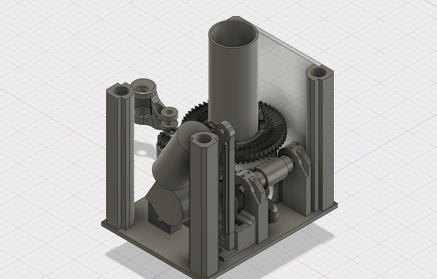
It is my design. I’ll post it somewhere when I have it completed. So far most of the pieces have been printed and a template of the base confirms the hole spacing. There’s still some details I need to work out, such as the 2.2:1 belt reduction combined with the 25:1 worm gear being enough with the Pololu motor driver to drive the tracker slow enough. I may have to add another belt reduction.
@kd8qwt This looks very good and promising. For the 2020 I think that is good idea to contact lulzbot. They built the TAZ printers with them, they are based in Colorado and they helped us in the a couple of times in the past. May they have to suggest a supplier in us. For the corners I think there is a good chance for the printed to work and we can try laser cut them too.
wondering how the 3d printed parts hold up to extreme weather. We get really hot summers here and potentially a lot of wet weather in the winter. What has been you experience? Would like to hear from anybody on here and also if anybody has used the carbon fiber filament?
 )
)