yes its possible. or dont cut, just use this 137 antenna for 433 freq. using the 3rd harmonic feature of the antenna. for example one of my station using single vhf v-dipole antenna, but can work also on uhf.
1 Like
found your station here
looking the obs, there is problem with your 70cm rx. do you use combiner? maybe you can try to test directly 70cm rx to your sdr without combiner, and see the result. check also the core pin of connector. maybe the pin loose
1 Like
Some remarks after looking at the meta data
radio: {
name: "gr-satnogs",
version: null,
parameters: {
mode: "GMSK",
soapy-rx-device: "driver=rtlsdr",
samp-rate-rx: "2.048e6",
rx-freq: "437252500",
file-path: "/tmp/.satnogs/data/receiving_satnogs_12874852_2025-12-04T19-38-25.out",
waterfall-file-path: "/tmp/.satnogs/data/receiving_waterfall_12874852_2025-12-04T19-38-25.dat",
decoded-data-file-path: "/tmp/.satnogs/data/data_12874852",
doppler-correction-per-sec: null,
lo-offset: null,
ppm: "0.448",
rigctl-host: "rigctld",
rigctl-port: "4532",
gain-mode: "Overall",
gain: "2.7",
antenna: "RX",
dev-args: null,
stream-args: null,
tune-args: null,
other-settings: null,
dc-removal: null,
bb-freq: null,
bw: null,
enable-iq-dump: "0",
iq-file-path: null,
udp-dump-host: null,
udp-dump-port: 57356,
baud: "4800"
}
},
The ppm value isn’t valid when using the RTLSDR and this driver it needs to be a integer.
Without any information on the complete RF chain I see that the gain value is very low.
Jan | PE0SAT
2 Likes
I use this thing I bought for 5 bucks at Aliexpress. Have a look at the first post of the thread. It pretends to be combiner with a filter for each band. I measured it with NanoVNA and the filter looks ok. But I will remove the combiner now and attache the V-Dipol directly to the LNA. Thank you for the feedback.
Thank you for the input. I changed the ppm to 1 and I will also give it a try without it. I have a RTL-SDR LNA power by BIAS-T at the antenna followed by 10 meters RG58. If I set the gain higher then 0.9 to 1.4 at the RTL, the noise floor will “jump” to -40db or worse and local radio will be distorted and dark red to black in the waterfall.
The whole chain was the QFH from my last posts and a V-Dipol, followed by the combiner (if it is one, you can see it in the first posts of the thread), then followed by a RTL-SDR LNA, then 10m of RG58, Bias-T Injector, Nooelec NESDR Dongle.
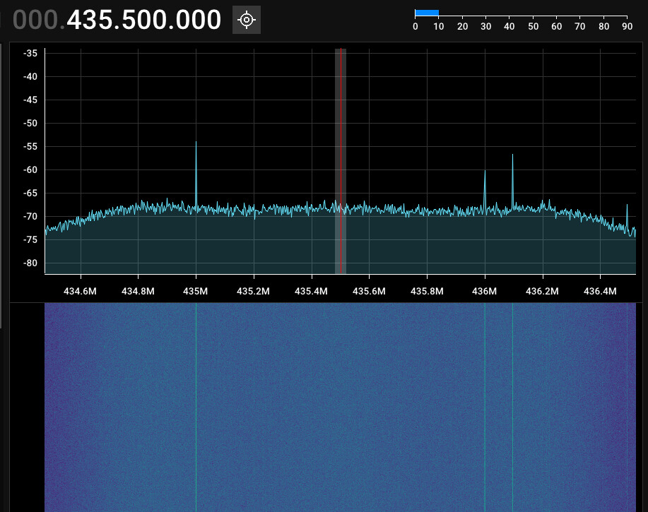
how is the waterfall diagram generated? Even if I set the gain very high it remains “darker blue”. Corresponding to the legend on the right it seems to be around -80 db. This is much less then I see in openwebrx if I tune the frequency. I don’t really understand this. I removed the combiner and attached the V-Dipol directly to the LNA and scheduled some passes.
That gain value can’t be right.
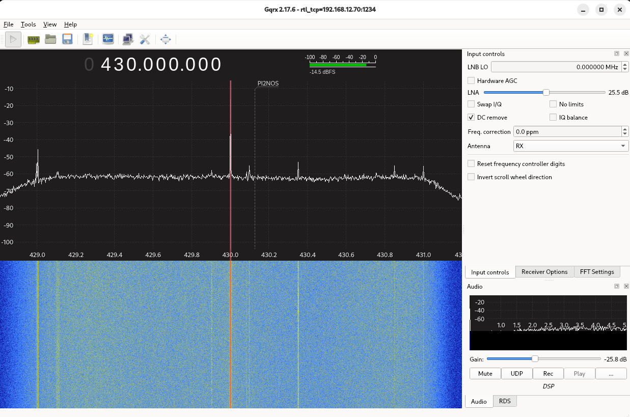
Here a ground station comparison (before I upgraded this setup with an Airspy Mini and 70cm EggBeater antenna.)
The SDR is a RTL-SDR v4, the LNA is a Nooelec LaNA being fed by a separate inline bias-t, 6 meter Aircell 7 and a 70cm Turnstile.
Configuration as can bee seen in the meta data:
{
radio: {
name: "gr-satnogs",
version: "v2.3-compat-xxx-v2.3.5.0",
parameters: {
soapy-rx-device: "driver=rtlsdr,serial=40000600,biastee=false",
samp-rate-rx: "2.048e6",
rx-freq: "435190000",
file-path: "/tmp/.satnogs/data/receiving_satnogs_12481803_2025-10-01T11-15-15.out",
waterfall-file-path: "/tmp/.satnogs/data/receiving_waterfall_12481803_2025-10-01T11-15-15.dat",
decoded-data-file-path: "/tmp/.satnogs/data/data_12481803",
doppler-correction-per-sec: null,
lo-offset: null,
ppm: "-3",
rigctl-port: "4532",
gain-mode: "Overall",
gain: "25.4",
antenna: "RX",
dev-args: null,
stream-args: null,
tune-args: null,
other-settings: null,
dc-removal: null,
bb-freq: null,
bw: null,
enable-iq-dump: "1",
iq-file-path: "/home/lab/431/data/iq/iq_431.raw",
udp-dump-host: "127.0.0.1",
udp-dump-port: 50431,
wpm: null,
baudrate: "9600",
framing: "ax100_mode5"
}
},
Below a pretty average spectrum when using the RTL-SDR with a 25.4 gain value and LNA.
Maybe the AGC option is enabled and is cause of the problems.
Jan | PE0SAT
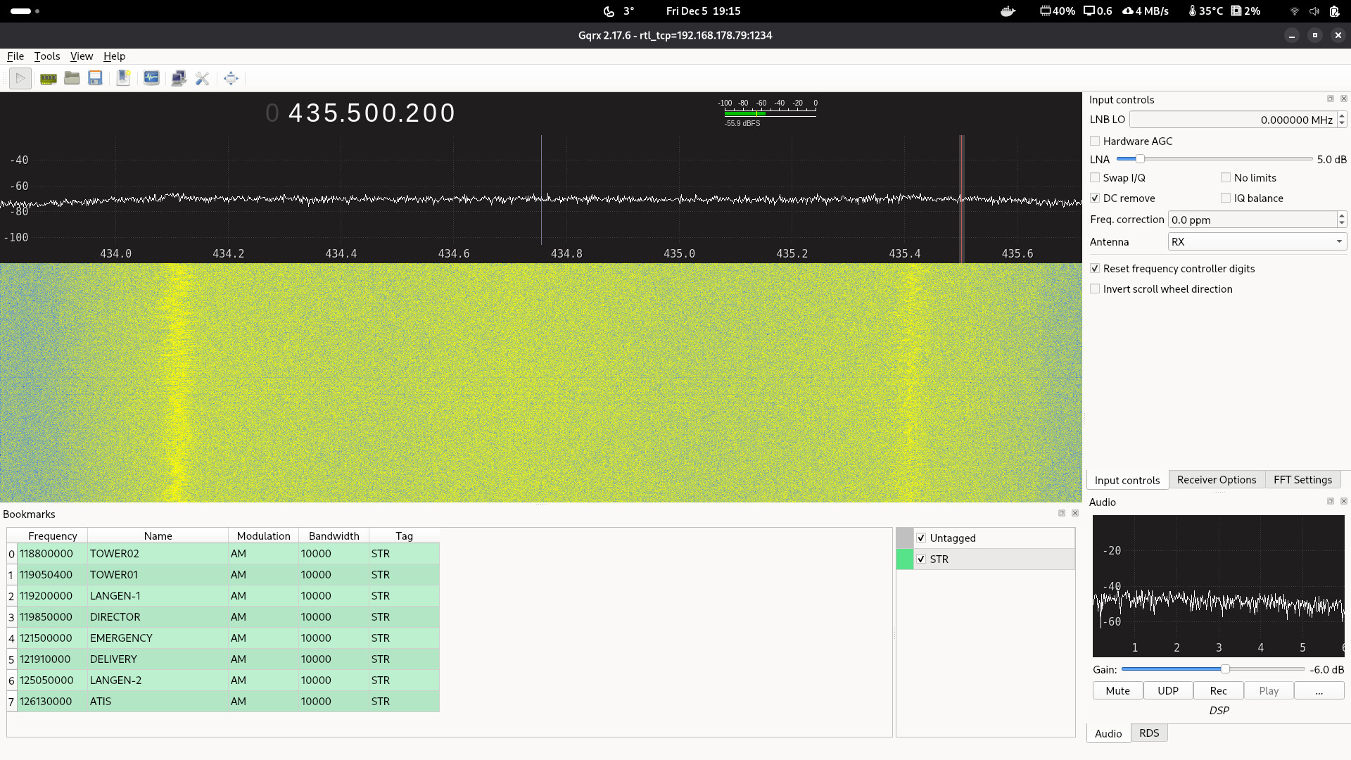
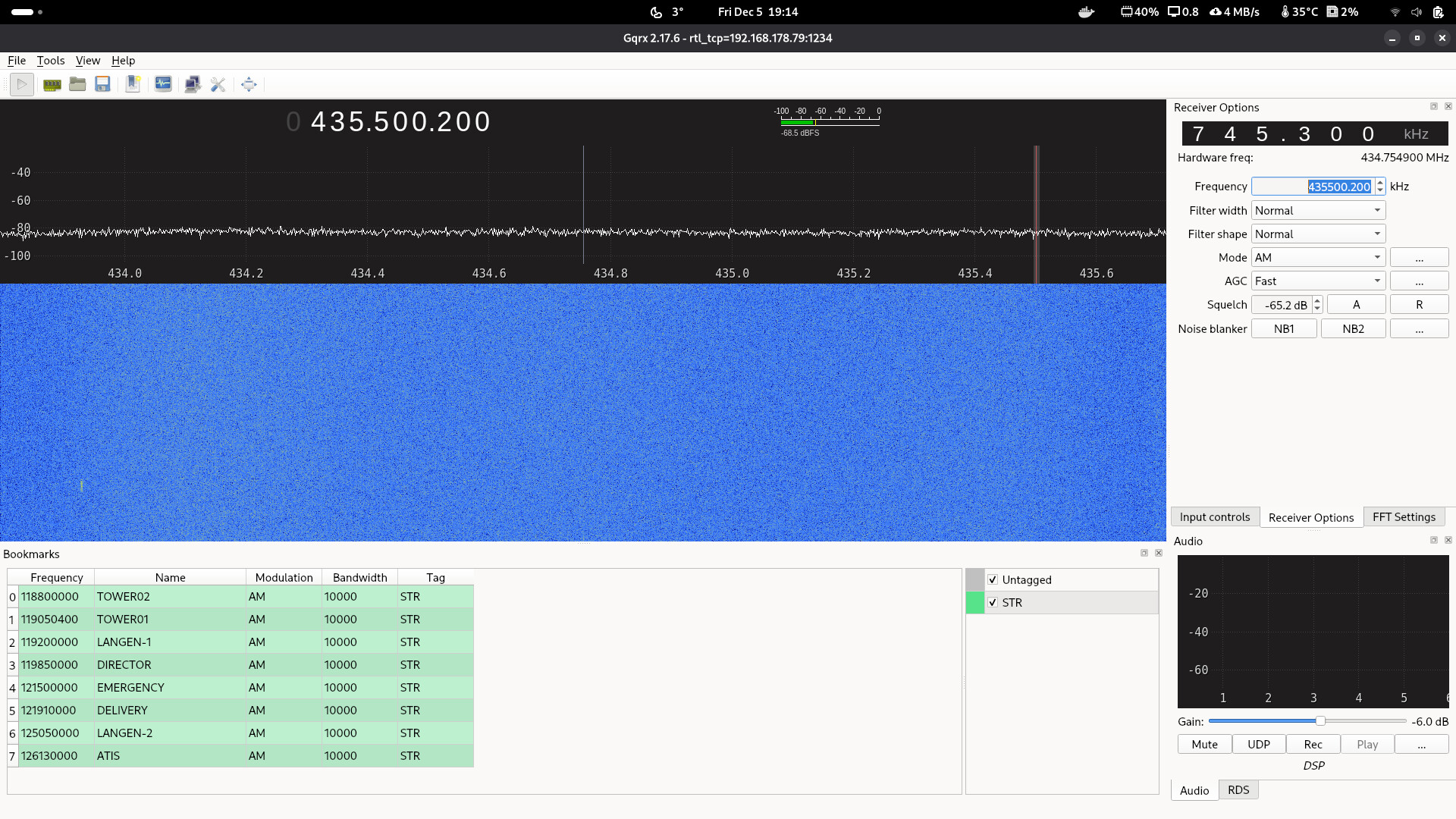
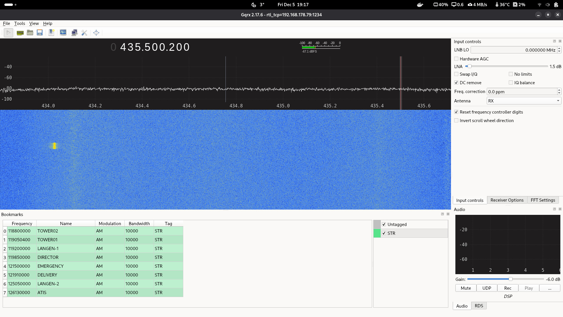
I started rtl_tcp on the pi and attached with gqrx. Here are some screenshots. As you can see the best SNR is around 0.0 to 2 gain. Should I remove the LNA?
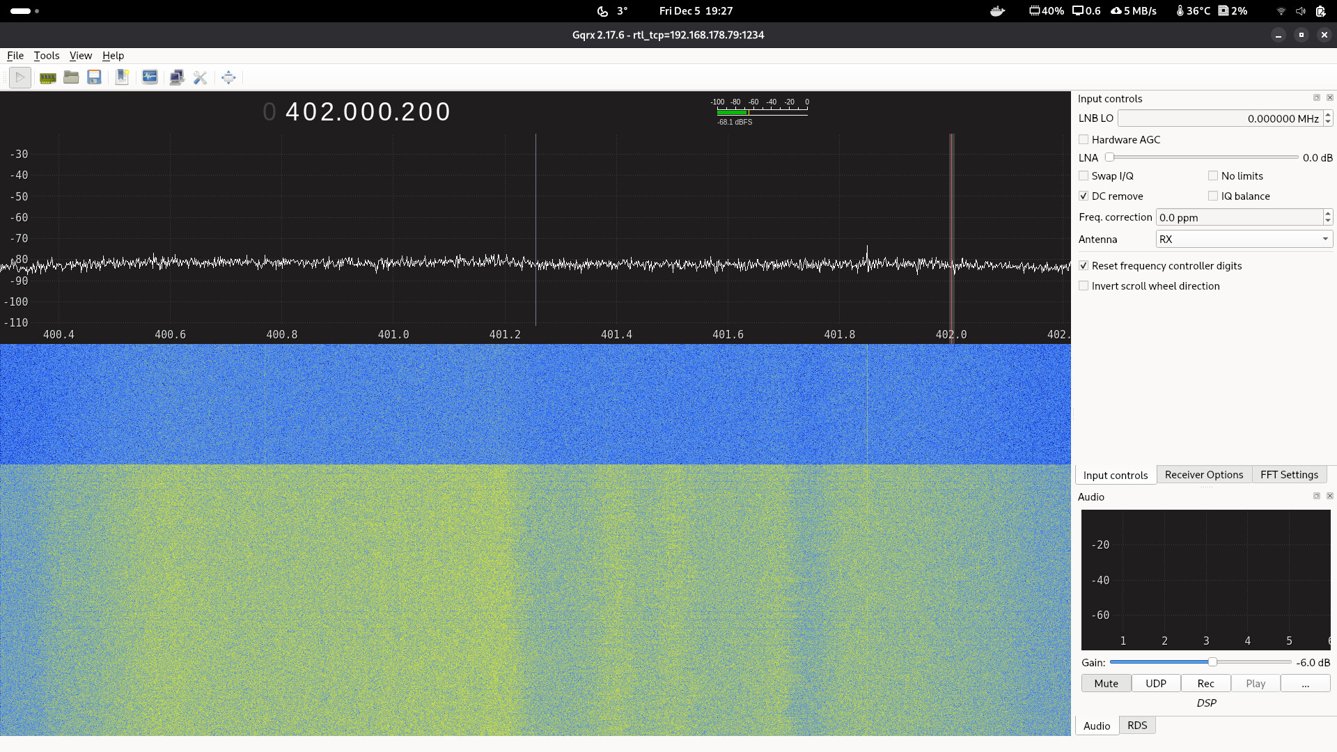
Don’t remove the LNA.
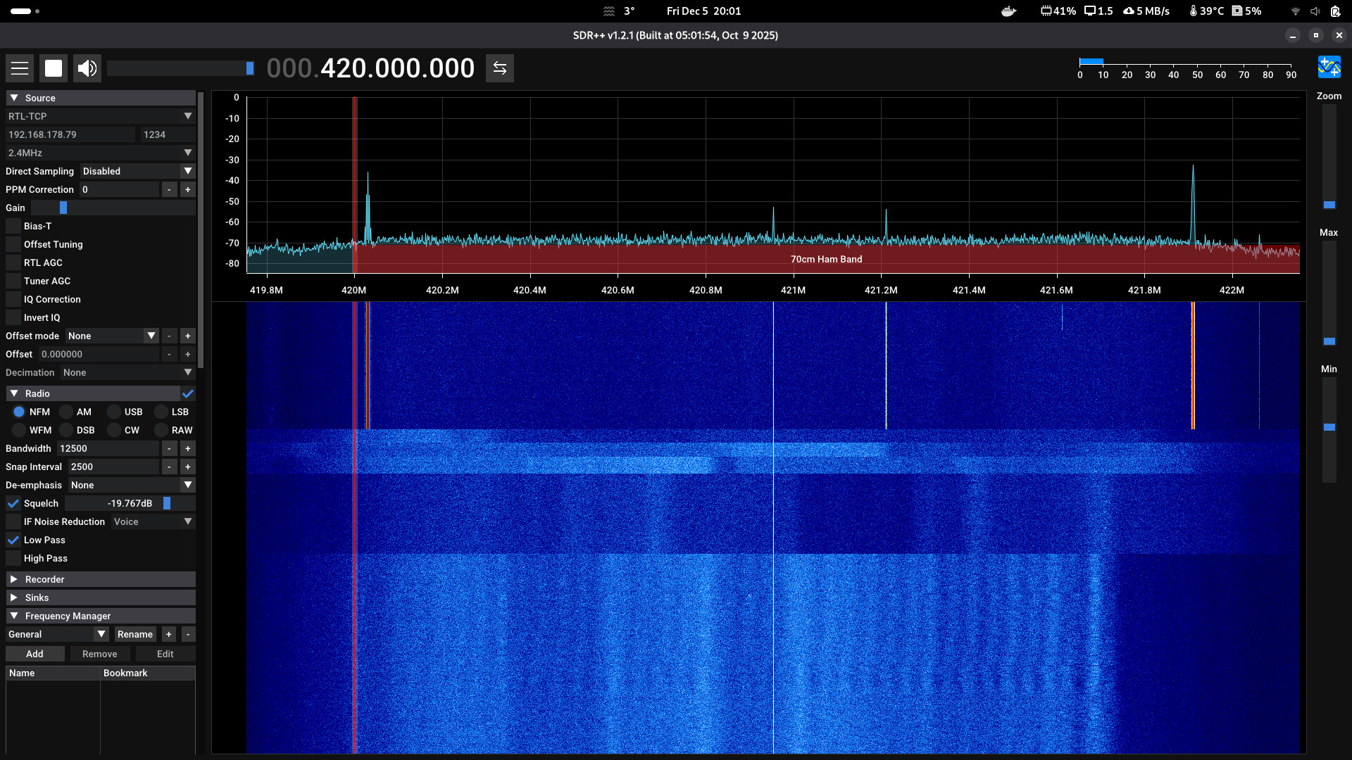
I gave GQRX a try and experienced very weird gain ruler behavior and DC remove wasn’t working can you also try SDR++
Jan | PE0SAT
GAIN Values:
Supported gain values (29):
 0 off
 1 0.0
 2 0.9
 3 1.4
 4 2.7
 5 3.7
 6 7.7
 7 8.7
 8 12.5
 9 14.4
10 15.7
11 16.6
12 19.7
13 20.7
14 22.9
15 25.4
16 28.0
17 29.7
18 32.8
19 33.8
20 36.4
21 37.2
22 38.6
23 40.2
24 42.1
25 43.4
26 43.9
27 44.5
28 48.0
29 49.6
Don’t use sample rates higher then 2.048e6, when you go higher you will experience aliasing.
For real observations also use decimation when using a SDR software solution such as SDR++ or GQRX.
Jan | PE0SAT
2 Likes
So something is received….. Unfortunately no satellite signal by now.
here i use rtl-sdr v4.
left with sample rate 2.048e6, and right with sample rate 3.2e6. from waterfall the higher sample rate have less noise than lower.
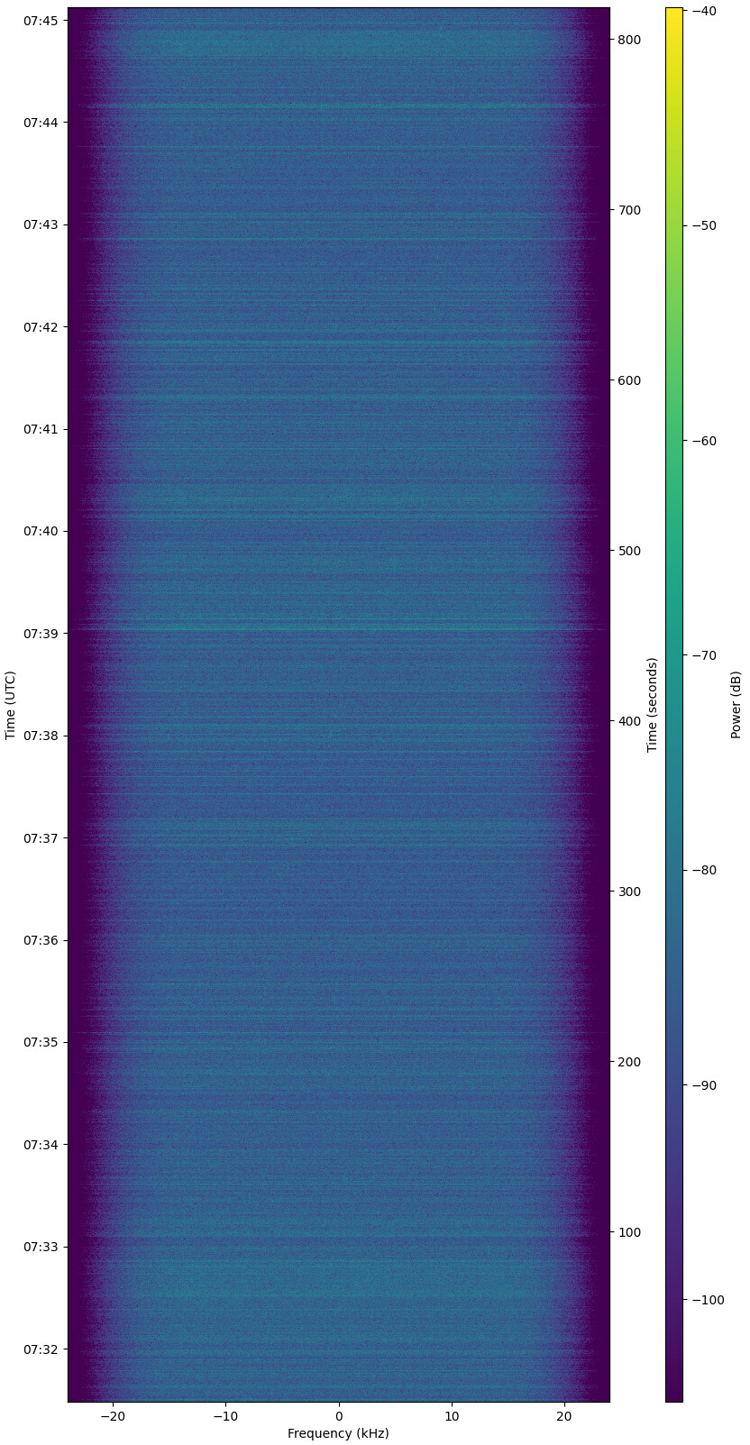
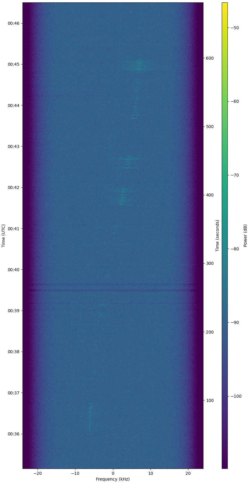
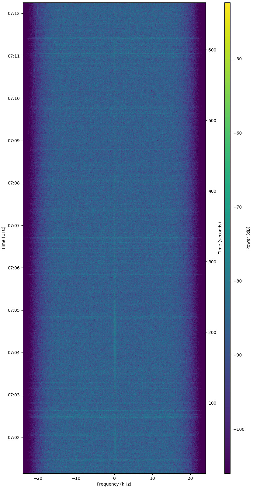

Thanks for sharing, you show that high sample rates and the resulting decimation ultimately lead to better results. But then you do need a SDR that isn’t susceptible for aliasing and the RTL is.
At the end it is a consideration between the decimation advantage compared to the risk that you receive aliased signals that aren’t really being received on the tuned frequency.
A side note, I have never seen a RTL-SDR successfully sample at higher frequencies then 2.56e6 above that values it starts to drop samples.
rtl_test -d 1 -s 3.2e6
Found 2 device(s):
  0:  RTLSDRBlog, Blog V4, SN: 40001150
  1:  Realtek, RTL2838UHIDIR, SN: 00000775

Using device 1: Generic RTL2832U OEM
Found Rafael Micro R820T/2 tuner
Supported gain values (29): 0.0 0.9 1.4 2.7 3.7 7.7 8.7 12.5 14.4 15.7 16.6 19.7 20.7 22.9 25.4 28.0 29.7 32.8 33.8 36.4 37.2 38.6 40.2 42.1 43.4 43.9 44.5 48.0 49.6
Sampling at 3200000 S/s.

Info: This tool will continuously read from the device, and report if
samples get lost. If you observe no further output, everything is fine.

Reading samples in async mode...
Allocating 15 zero-copy buffers
lost at least 824 bytes in buffer 0
lost at least 972 bytes in buffer 1
lost at least 1024 bytes in buffer 2
lost at least 612 bytes in buffer 3
lost at least 648 bytes in buffer 4
lost at least 1244 bytes in buffer 5
lost at least 972 bytes in buffer 6
lost at least 648 bytes in buffer 7
lost at least 408 bytes in buffer 8
lost at least 1280 bytes in buffer 9
lost at least 648 bytes in buffer 10
lost at least 1092 bytes in buffer 11
lost at least 904 bytes in buffer 12
lost at least 1484 bytes in buffer 13
lost at least 1296 bytes in buffer 14
lost at least 800 bytes in buffer 15
lost at least 852 bytes in buffer 16
lost at least 784 bytes in buffer 17
lost at least 800 bytes in buffer 18
lost at least 972 bytes in buffer 19
lost at least 1160 bytes in buffer 20
lost at least 664 bytes in buffer 21
lost at least 1040 bytes in buffer 22
^C
Signal caught, exiting!

User cancel after 23 buffers, exiting...
Samples per million lost (minimum): 3504
Jan | PE0SAT
2 Likes
you right. i try running this tool, set the sample rate to 2.88 and 3.2 and the samples are drop. now i change my station to 2.56e6
some progress: it seems that the v-dipol is the problem. If I only attach the QFH to the combiner the signal strength is MUCH higher. If I attache an other antenna to the VHF port everything is fine but if I attach the v-dipol, the whole signal get’s blurry and looses around 15 db.
1 Like
we rebuilt the v-dipol. now it measures fine. But it still seems that attaching the v-dipol is “saturating” the SDR. Is this possible? I need to set the gain on the SDR to zero (as before) and I still have very high signal levels in GQRX for local RX in 2m and 70cm. I meanwhile noticed that music seems to play in the very wideband noise (up to -40dB) in 2m and 70cm. So i assume that the v-dipol works (very) well but the nearby UKW and DAP radio tower is saturating my input stage. Should I add a FM blocker to the chain? Only on the VHF input or after the combiner? If the 433 Mhz QFH is the only attached antenna, then the filter in the combiner seems to compensate the effect I am seeing now.