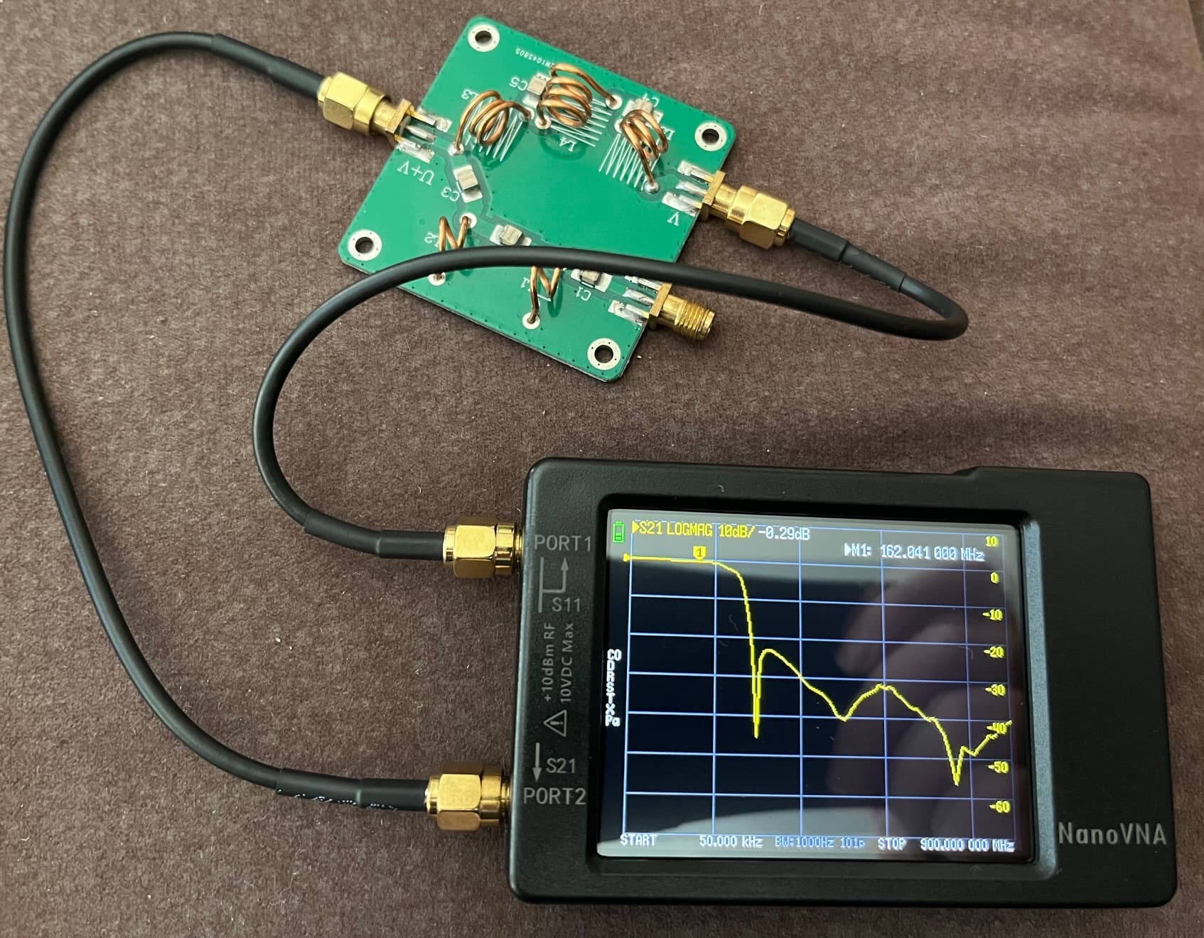
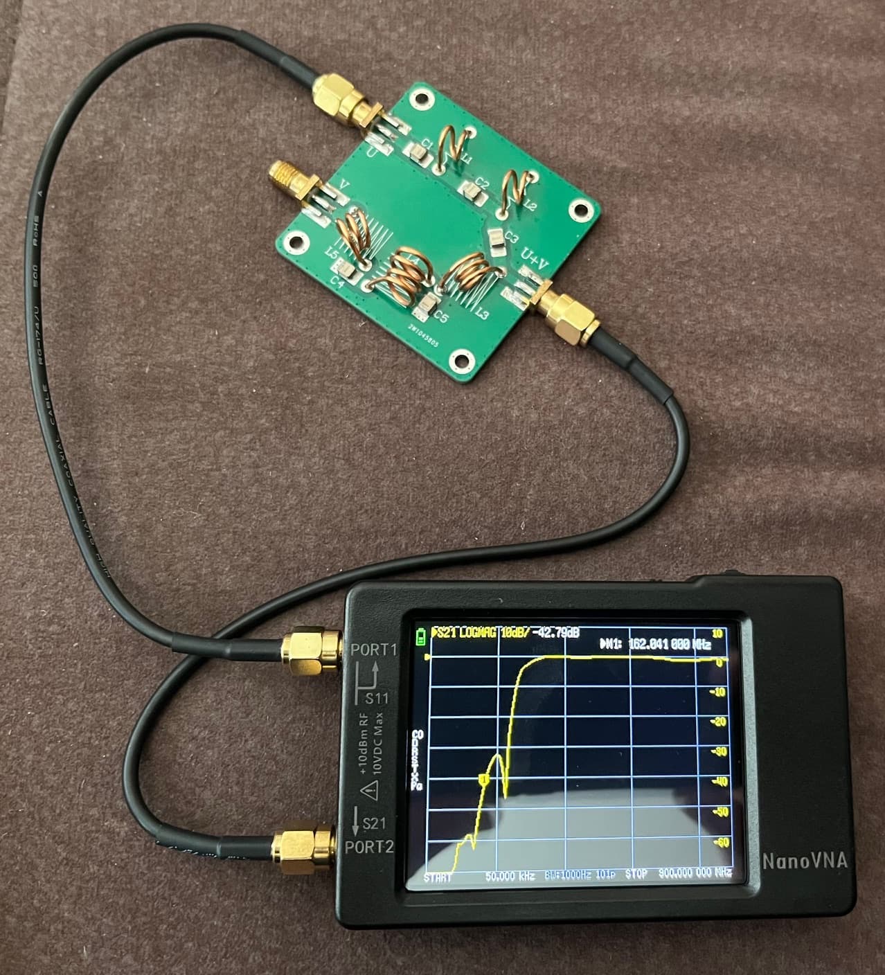
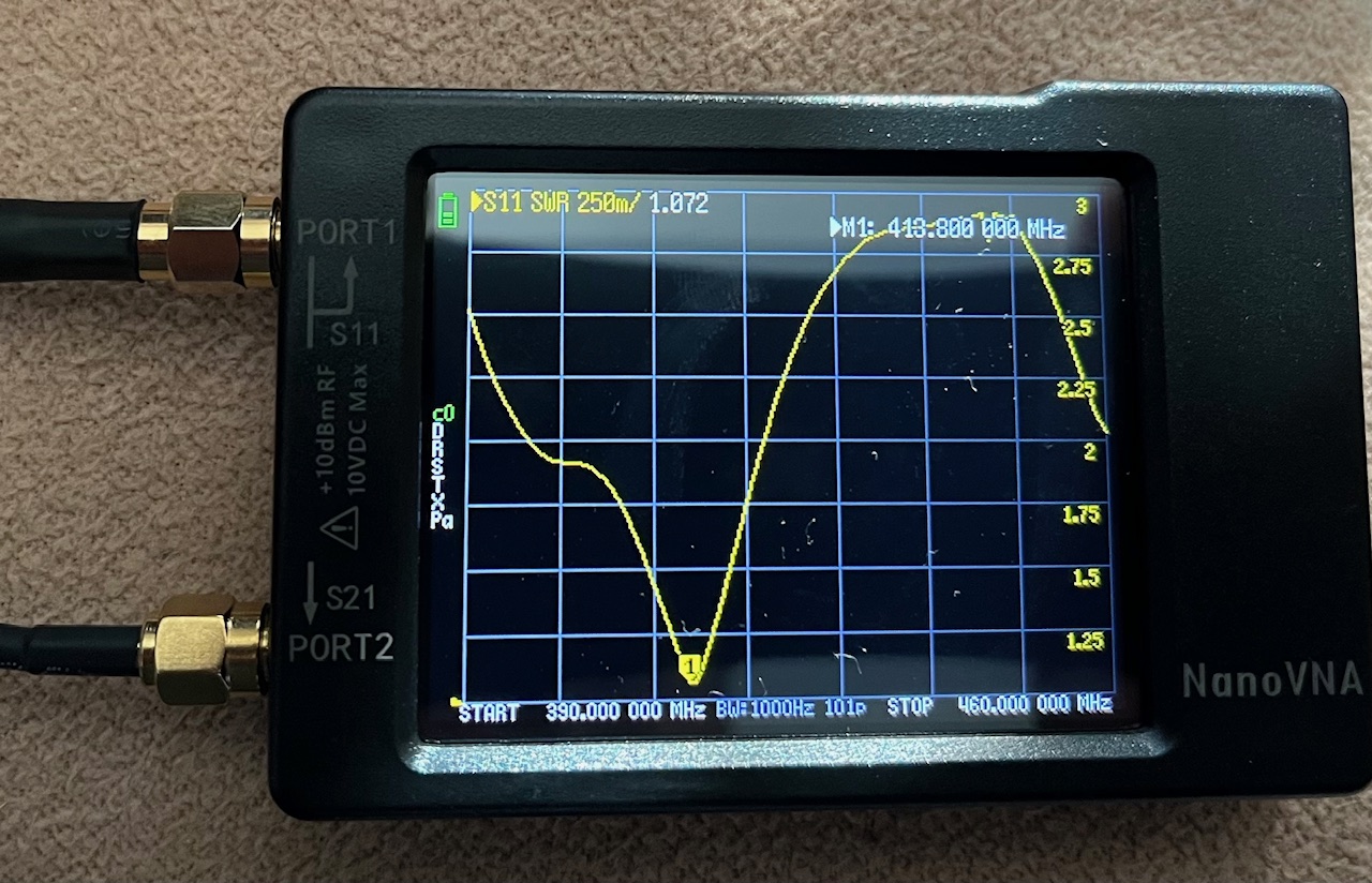
we started to build our groundstation. We use Pi 3B with trixie OS and the 2.x client docker image. Attached to a NeSDR Smart. We already have a VHF V-dipol from the Raspberry NOAA project. Now we bought a cheap VHF/UHF filter/combiner. It has a VHF Input filtering all above around 260 Mhz and a UHF input filtering everything below. Here are some NanoVNA measurements.
It look OK to us but we are not very experienced in ready VNA data. therefore any criticism or support is welcome.
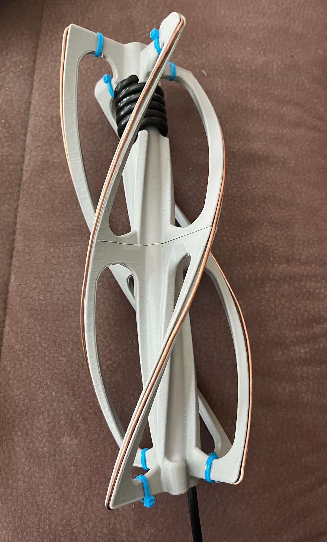
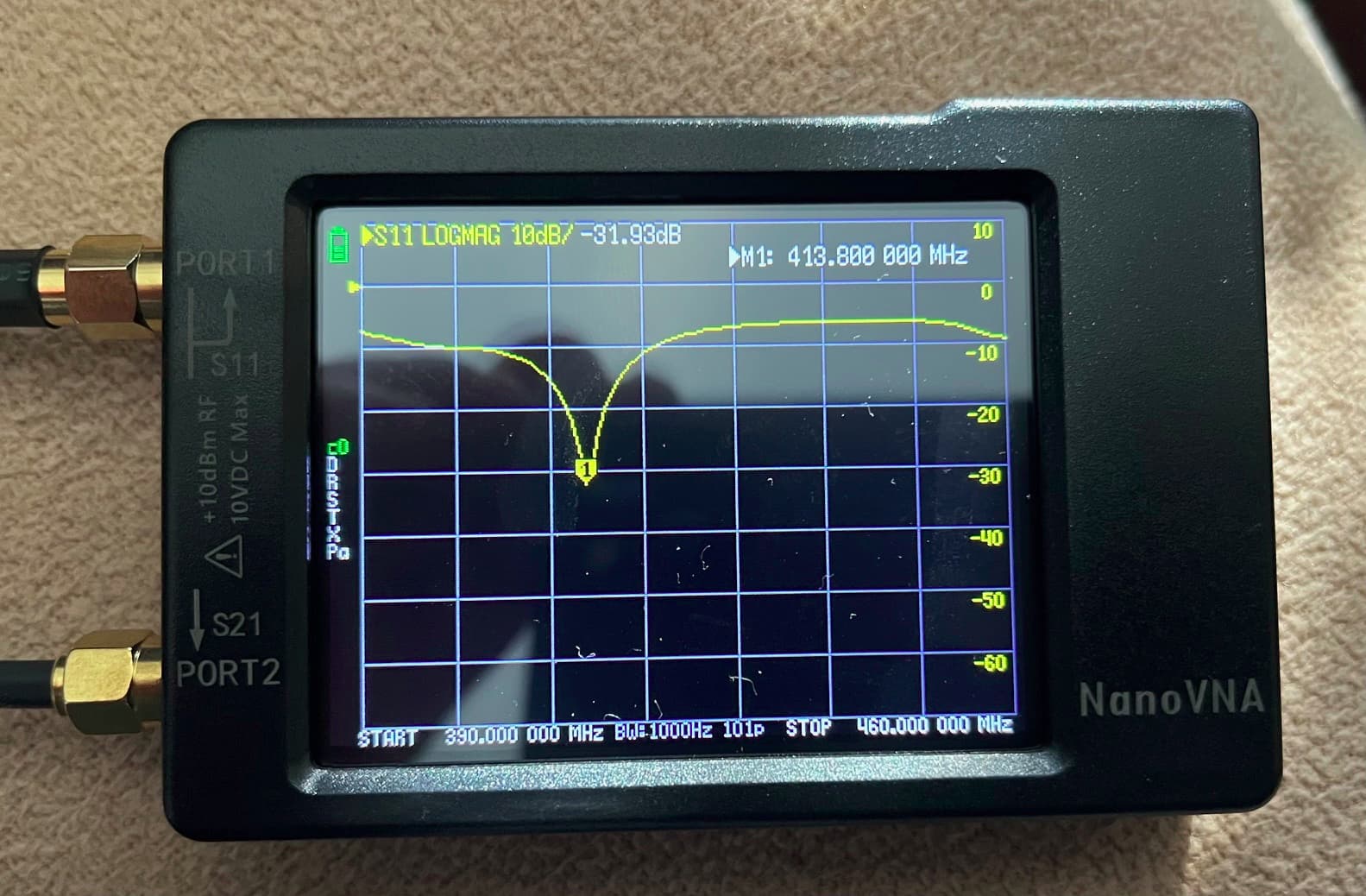
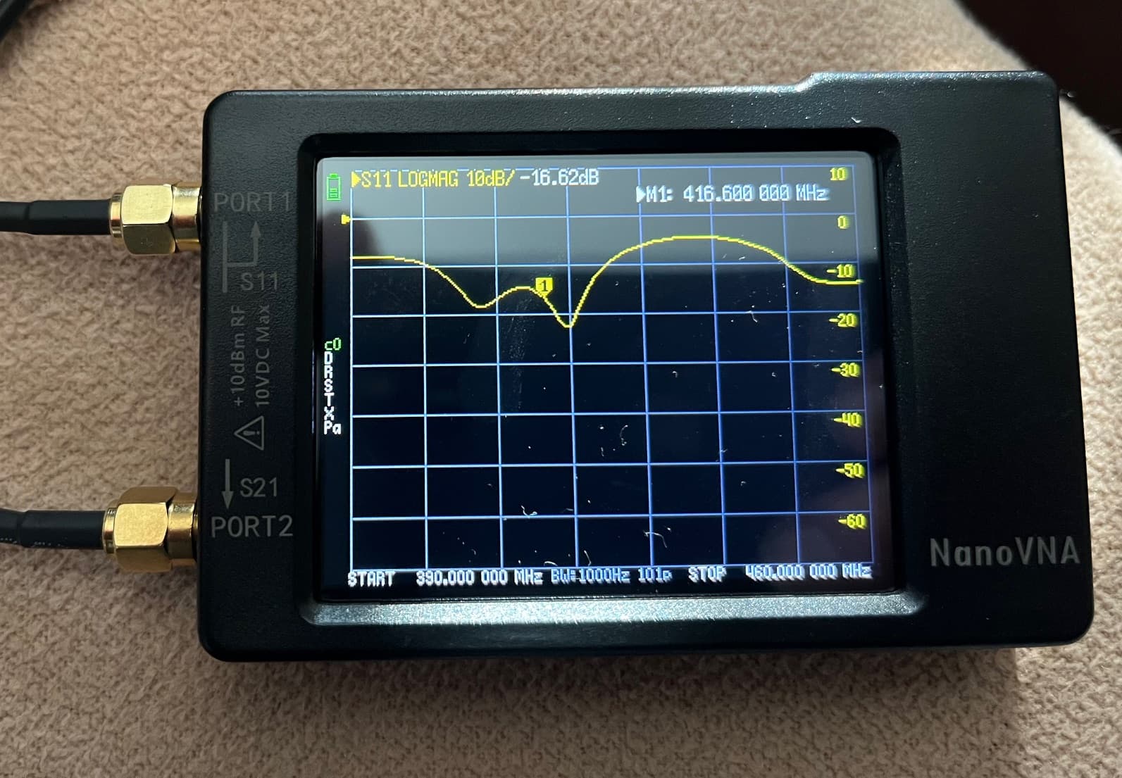
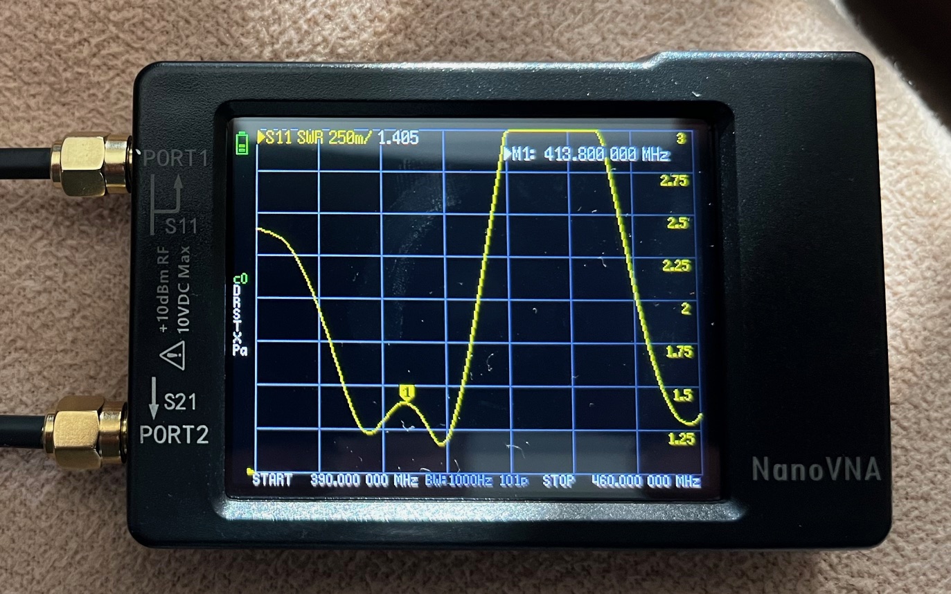
Then we printed and assembled our first 433 MHz band QFH antenna. We also measured this with the VNA. However, we can’t really form an opinion as to whether it’s good or bad. We measured the antenna with and without the filter. I’m posting the pictures here in the hope of some opinions on whether it’s any good or not.
We’ve already printed a second 433 MHz QFH. We still need to assemble it. The idea is to have the V-dipole at the bottom of the mast and then the QFH above the V-dipole. Is this a good idea, or should the antennas be spaced further apart? Both antennas should then be connected to the UHF and VHF inputs of the filter board, respectively, and then a roughly 7.5m long cable should be connected to the SDR module. Does this make sense?
I think the stacked design should work just fine. Mount them at least a quarter wavelength (at the lowest freq) apart for good measure. And measure the antennas when mounted together.
When mounting side to side, I usually try to think of stacking distance, but this is usually much longer than absolutely needed for two antennas on different bands. 1-2m away for a 145MHz antenna I’d say is the minimum for omni’s.
Try to put a LNA at the combined port, that is a good investment.
Regarding the swr at 418MHz, I think this is due to the amount of dielectric (plastic) close to the antenna elements, I consider the QFH a wide RX antenna, so for reception this should not be too bad. Transmission is another thing.
I have one that I use from 400-490MHz but was made for 400-450MHz, iirc also a bit low in frequency but that was a good thing in my case.
Thank you @SA2KNG. I have two Nooelec LANA from the ADSB and the NOAA projects. I plan to use one in the new setup. But I fried my Bias-T or, more precisely, water got into the connectors or the cable somewhere and killed the bias-T. I need a new bias-T first, and this time I want one that’s not in the RTL stick, so the entire stick doesn’t break if there’s another short circuit. What would be a good solution to protect the receiver dongle from those incidents?
I usually just have a external bias-tee and feed it filtered 5V or 12V depending on the LNA.
You can see them in the station picture.
A small and fast fuse is also a pretty good investment (:
The ground station setup shown in your photo is truly impressive! It looks so clean and linear. Congratulations on the build progress!
Do you happen to have a guide or an article detailing the components and the overall setup? I’d be very interested in learning about the specific technical choices you made regarding the type of antennas and LNAs. I see fuses in the small board underneath the power supply box, right?
I have some documentation, but I have not aimed at something like a complete manual on how to build another one. It usually lacks the things I take for granted, but might not be obvious to others.
There’s some older pics and from the build in my photo album.
Very nice station. Thank you for the tips. I am busy the next few days but I am already tinkering around with openscad to build some holders to fit everything together. Do you filter the power with ferrit beds or do you use any active filering, too?
P.S. I assume the breadboard lower left is some sort of active filter?
It’s a passive LC with a linear regulator for 12->5V
Ferrites/chokes is your friend, well worth having a bunch of and testing where they make a difference. Don’t underestimate a proper groundplane as well.
The coaxes are custom built RG-405 cables and connectors. You need a proper coax stripper else it will be painful, I use the LC CST-MINI. Buying a bunch of RG-405 SMA, N and coax will last you a long time and be pretty cheap in the long run compared to pre-made RG-316 stuff.
Thanks.
Yes, it is one Pi4 4GB and 3 rtlsdr. I have tested running three simultaneous satnogs-client, and also a mix with satnogs radiosonde_auto_rx and openwebrx.
Memory and cpu performance has been shown to be sufficient.
The system has evolved a bit, where the second antenna input is not used and all sdr’s are connected to the same antennas. Due to the high amplification from the LNA’s, the signal splitter is not degrading the performance.
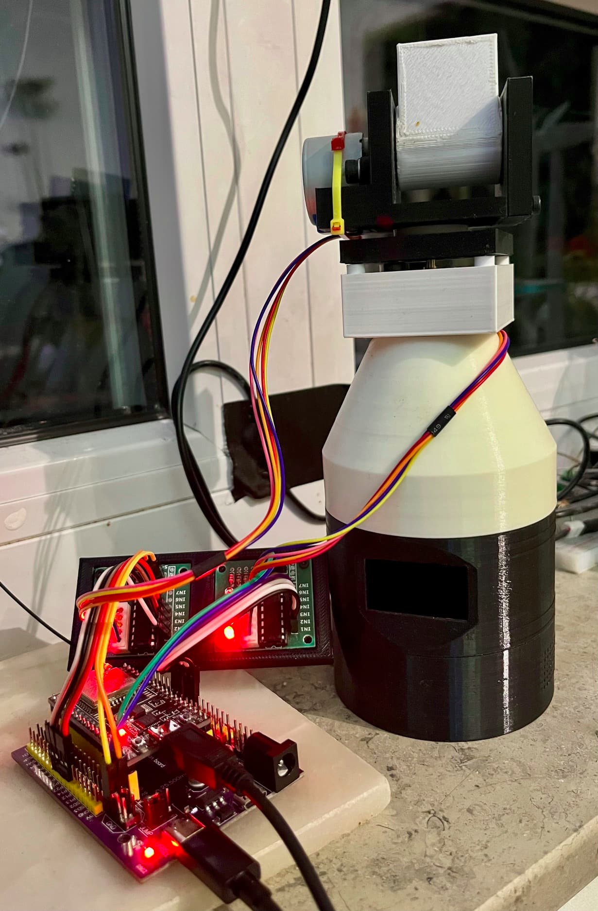
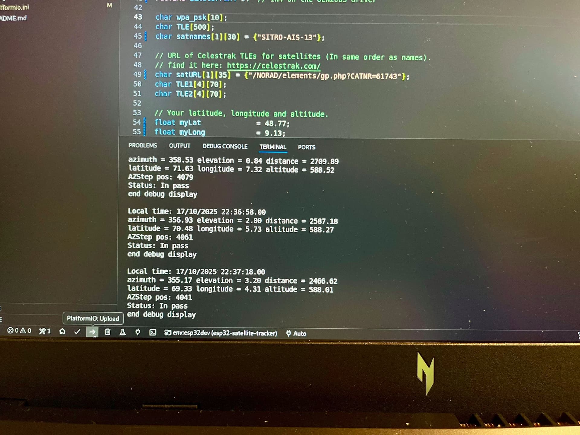
While I’m waiting for some parts to assemble the antenna outdoors, I’ve taken my old satellite tracker project out of the box again. I ported the code to an ESP32, and it’s working again. This will refresh my knowledge of TLE and track structures a bit. Starting tomorrow, I’ll be printing a new “dish.” The original project can be found here: Satellite tracking antenna model by yychang - Thingiverse.
I’m currently considering whether a DLC32 might be a great hardware platform. It’s actually for a 3D printer or CNC machine. It’s ESP32-based and already designed for up to three steppers and limit switches. It has a 3.5-inch display with LVGL support. Cost less the 30 Euros. This would also allow the use of large stepper motors that could then support a Yagi.
That is a really well-made model! It would be great to scale it up to mount a real Yagi antenna on it!
We definitely need more low-budget satellite tracking experimentation. Don’t get me wrong, the Satnogs Rotator v3 is great, but with the component count, it’s a big project, and for someone new like me, it’s easy to feel overwhelmed.
I’ve been looking for something more plug-and-play, maybe using a security camera mount. I know Gabe from the YouTube channel saveitforparts built one in the past using some SARCTRAC Python code. Unfortunately, it’s been a while, and there isn’t a lot of current information on which mounts are compatible.
I’m still not entirely clear on how a rotator is connected to Satnogs. My project pulls a few TLEs itself and then processes them. The ESP32 is somewhat limited by RAM, so there aren’t that many satellites that can be installed.
As far as I understand, it would be better if the rotator could be connected directly to Satnogs. Since the ESP32 module has Wi-Fi and a comprehensive IP stack, you could, for example, transmit rotator data via Wi-Fi and use the existing stepper code for positioning. This already takes elevation and azimuth. Whether they come from the predict function or from Satnogs is irrelevant.
I now need to check whether a LAN connection from a rotator is supported in Satnogs and what protocol is used. If anyone can elaborate on this, that would be very helpful.
Unfortunately, my engineering knowledge is quite limited. Therefore, I’m having a hard time estimating how powerful the motors need to be to hold, for example, a 70cm Yagi. There are also questions like water resistance and wind load if it’s intended for permanent outdoor installation. But I can easily imagine building an indoor version first, and then maybe someone can make it more stable and powerful.
This was much easier than I thought. There are several Arduino implementations of rotctld, or at least parts of the protocol. It was relatively easy to port to an ESP32. There’s also a simple example here: GitHub - ch3p4ll3/ROTCTL-ESP: a simple rotctl server for ESP-32.
This, combined with the existing stepper code, works. I can connect the rotor to the Wi-Fi network and then enter it into gpredict. Then I can track via gpredict. There are still many problems. For example, initialization, positioning, or preventing the azimuth from rotating more than 360 degrees and then winding up the cables :).
Yes, I’d say that implementing hamlib protocol is the simplest solution. very universal for a lot of projects. some do implement a rotator protocol like gs-232 or easycomm, but I think this is a detour when having wifi/lan enabled platforms that can speak hamlib straight up.
do note that there’s hamlib protocol variations, so make sure to match the library version and in the controller.
Thank you for the tip. Is it possible that not all satellites in the Stanogs database support tracking? I keep having the problem that the satellite isn’t tracking. I see that the hamilb is connected and the start position is set, but then no updates occur. I also don’t see any position messages from Satnogs in the ESP32 logs or in the tcpdump. How can I investigate this further? Is there any way I can enable debug logging in the Docker image so I can see why there are no more updates?
This is a timelapse of a recent Crocube pass, controlled by my Satnogs. But as mentioned, it does not work all of the time from statnogs. But without issues in autotrack from gpredict so far.