Just hold down your left mouse button and rotate away
wont work .
A former co-worker created a drawing using Alibre. I think this is the correct placement
Motormount Gear1.pdf (924.6 KB) Its a PDF with 3D model ioncluded
Mareike
You can adjust the distance between motor pulley and worm gear pulley. Take a look here, steps 14, 15.
1 Like
Hi Mareike,
Have a look at the third photo down is this link.
https://community.libre.space/t/version-3-1-axis-gear-and-axis-side-are-offset-from-each-other/1231
Shows where to mount the stepper.
Hope this works my first post to this community.
Steve
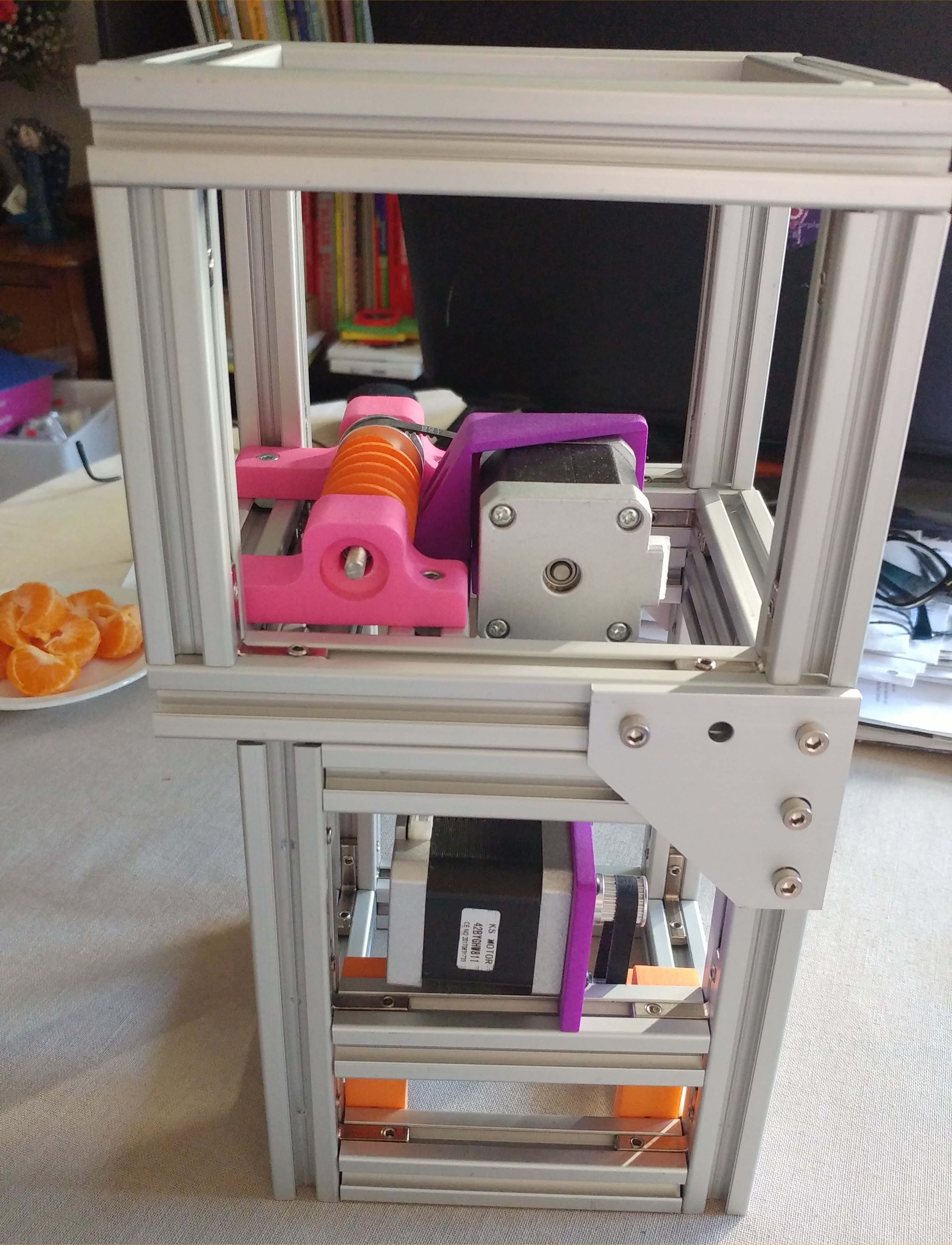
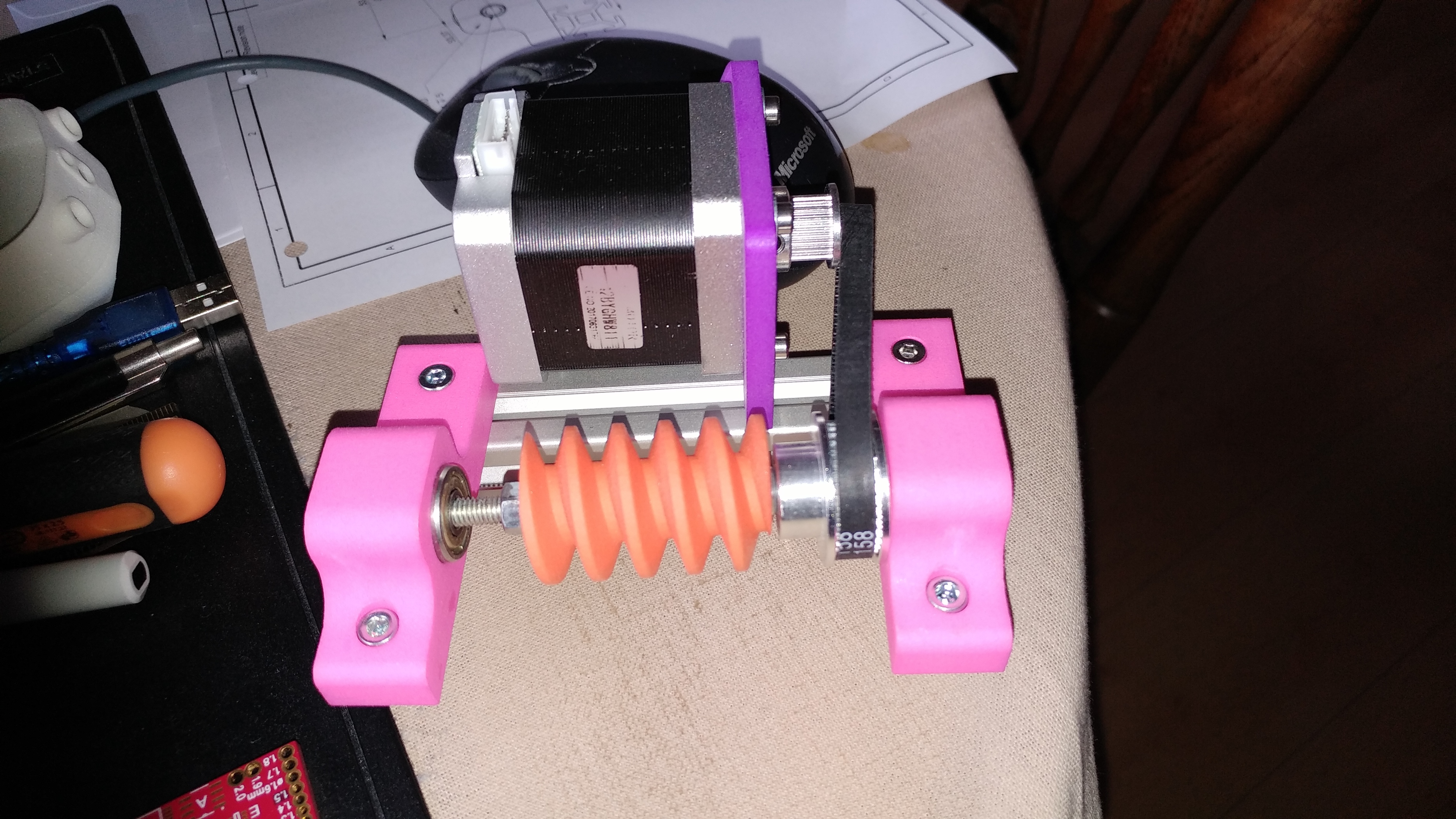
Yesterdat I got the new motor-mount as pictured here:
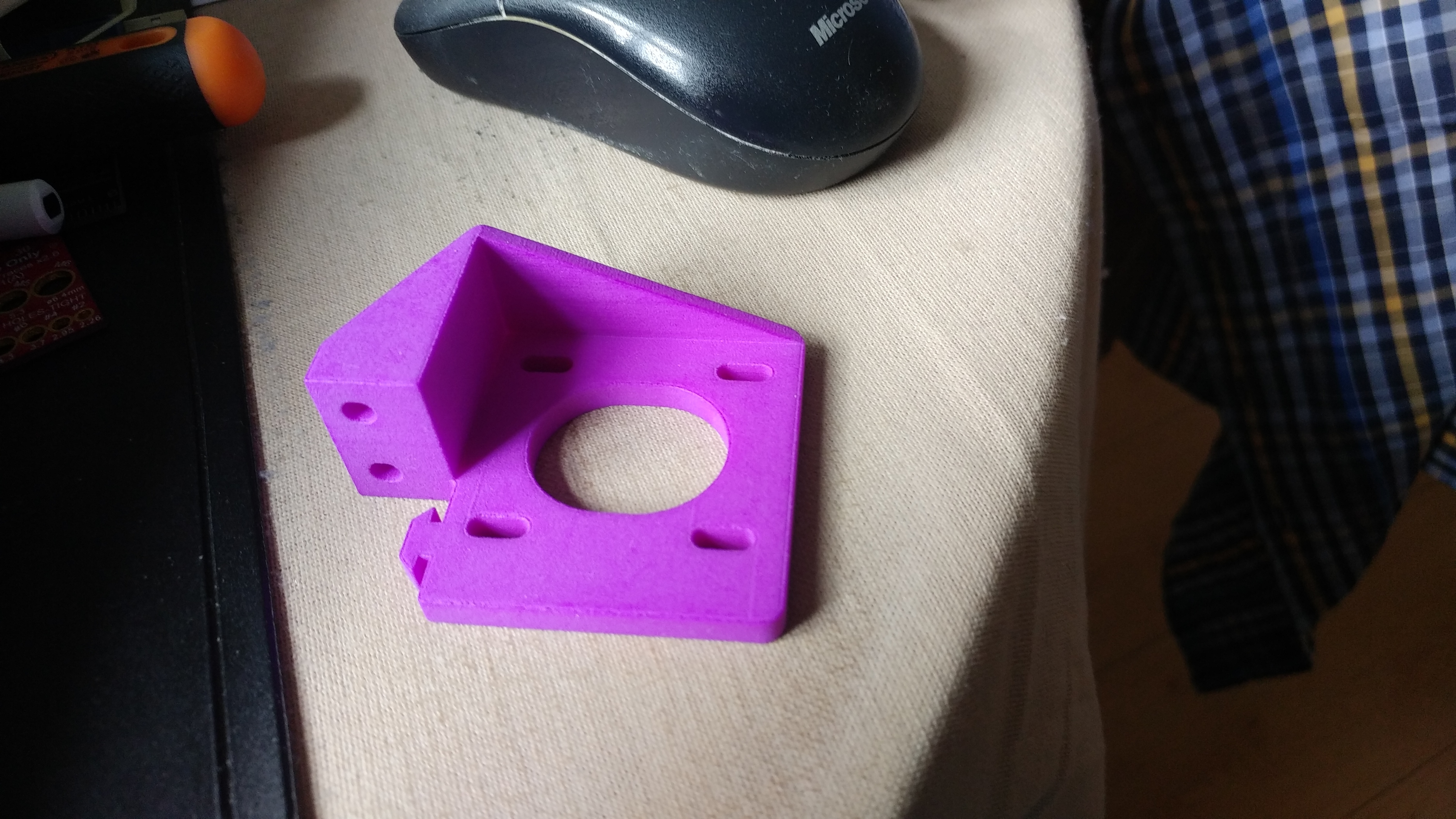
Ans then I mounted it expecting it to fit snugly into the frame. THE MOST DISAPOINTING CAME THEN. iT dOENST FIT AT ALL,

Not even the stepper fits as can be seen here:
So from this moment on I desided that I wil lreave this project and trow away all OI have. Sorry to say as it looked to be a prommesing project as I cannot findout/see what I am doing wrong??!!
Mareike
Hi Again Mareike,
The purple Plastic part in the above Picture is correct I believe.
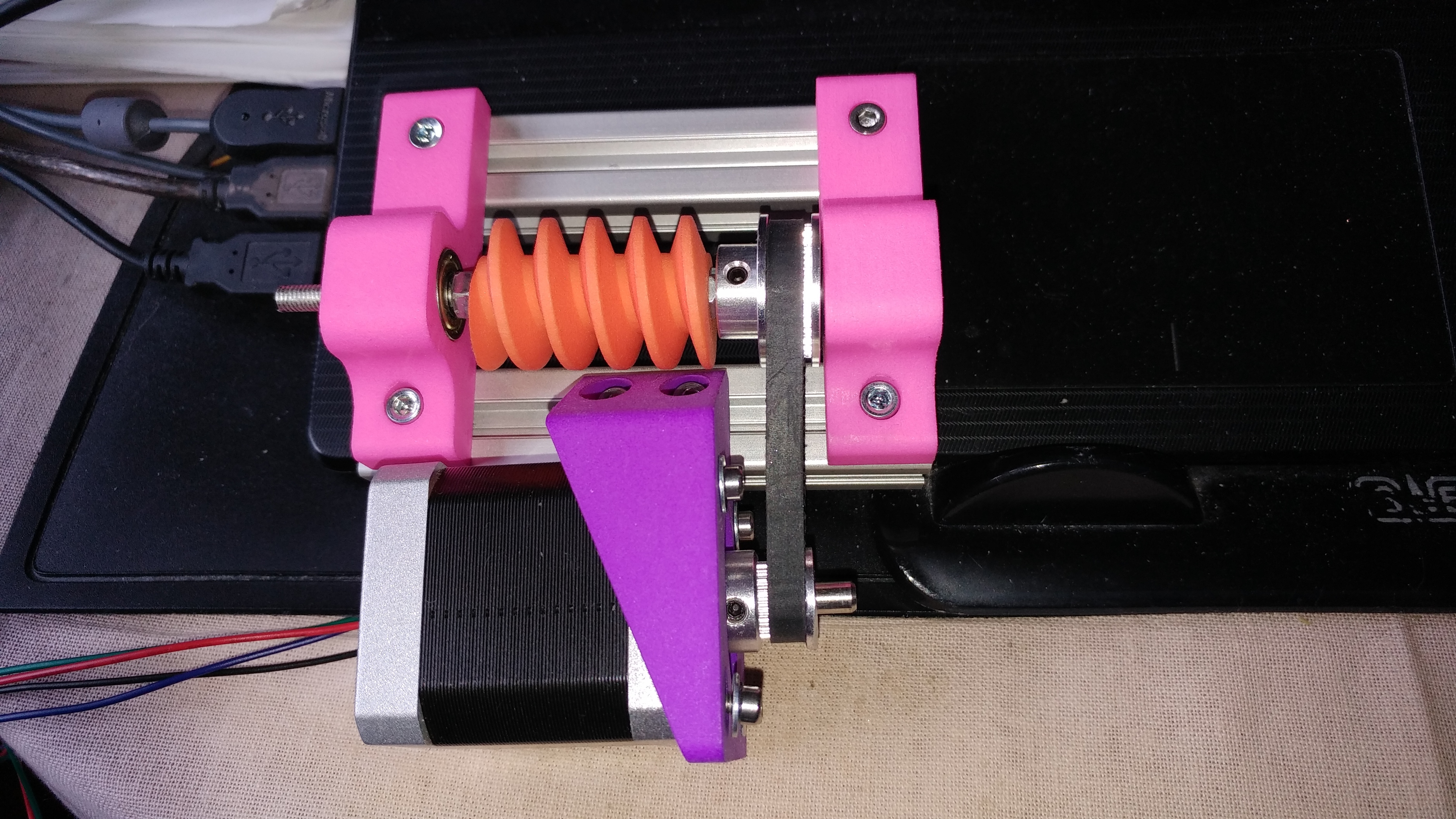
It appears in the other photos that the whole worm gear, shaft and pulley needs to be flipped 180 degrees, from front of picture to back of picture.
Flip the mount in the same direction, putting the mounting bolts in slot closest to worm gear.
The stepper should fit then.
Also the pink bearing mounts seem to be swapped as well.
Change them so the bearing holes are towards the shaft.
I hope this makes sense to you.
Again look at the earlier photos in this post as it will help.
Steve
Hi Steve,
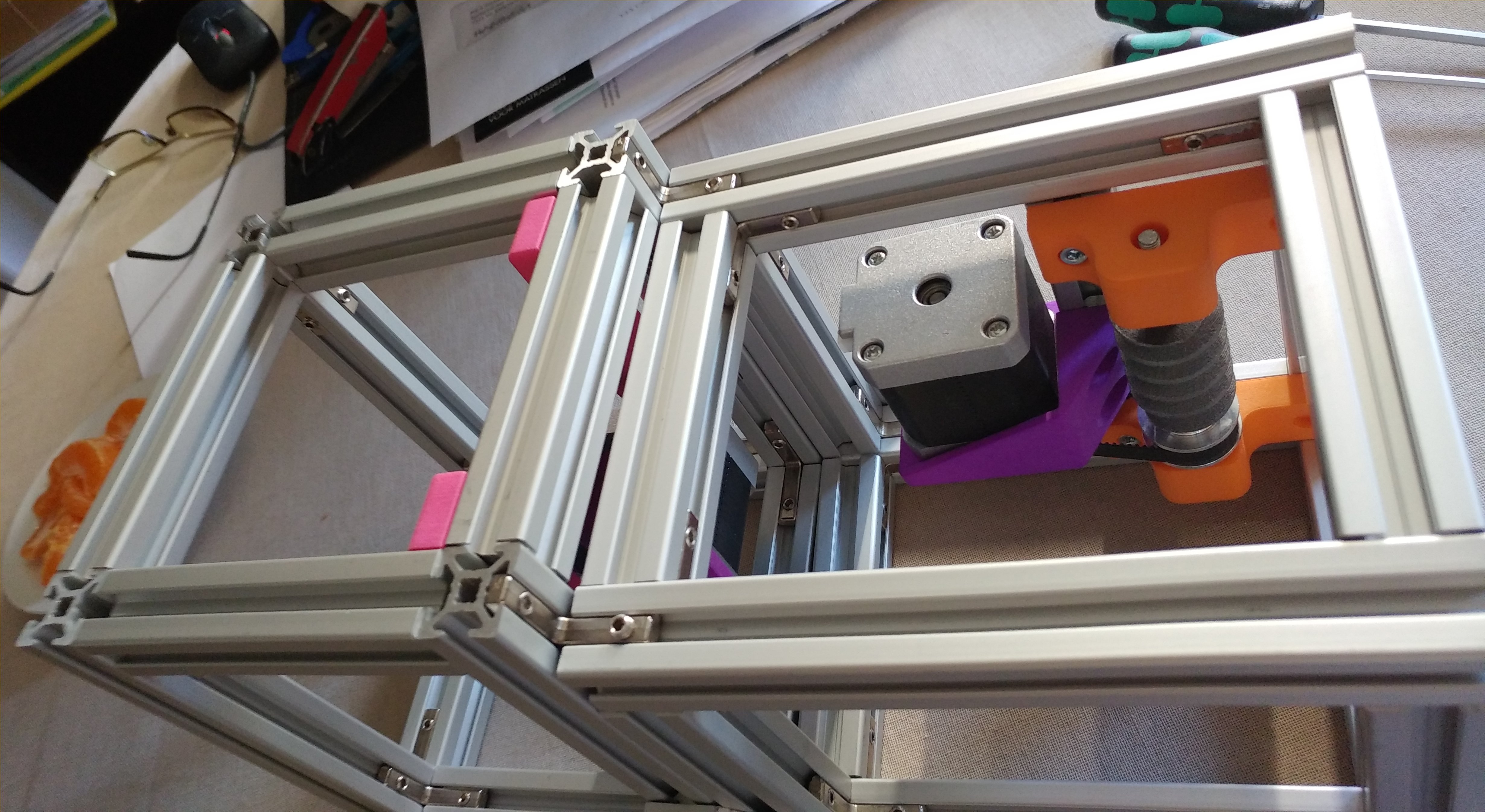
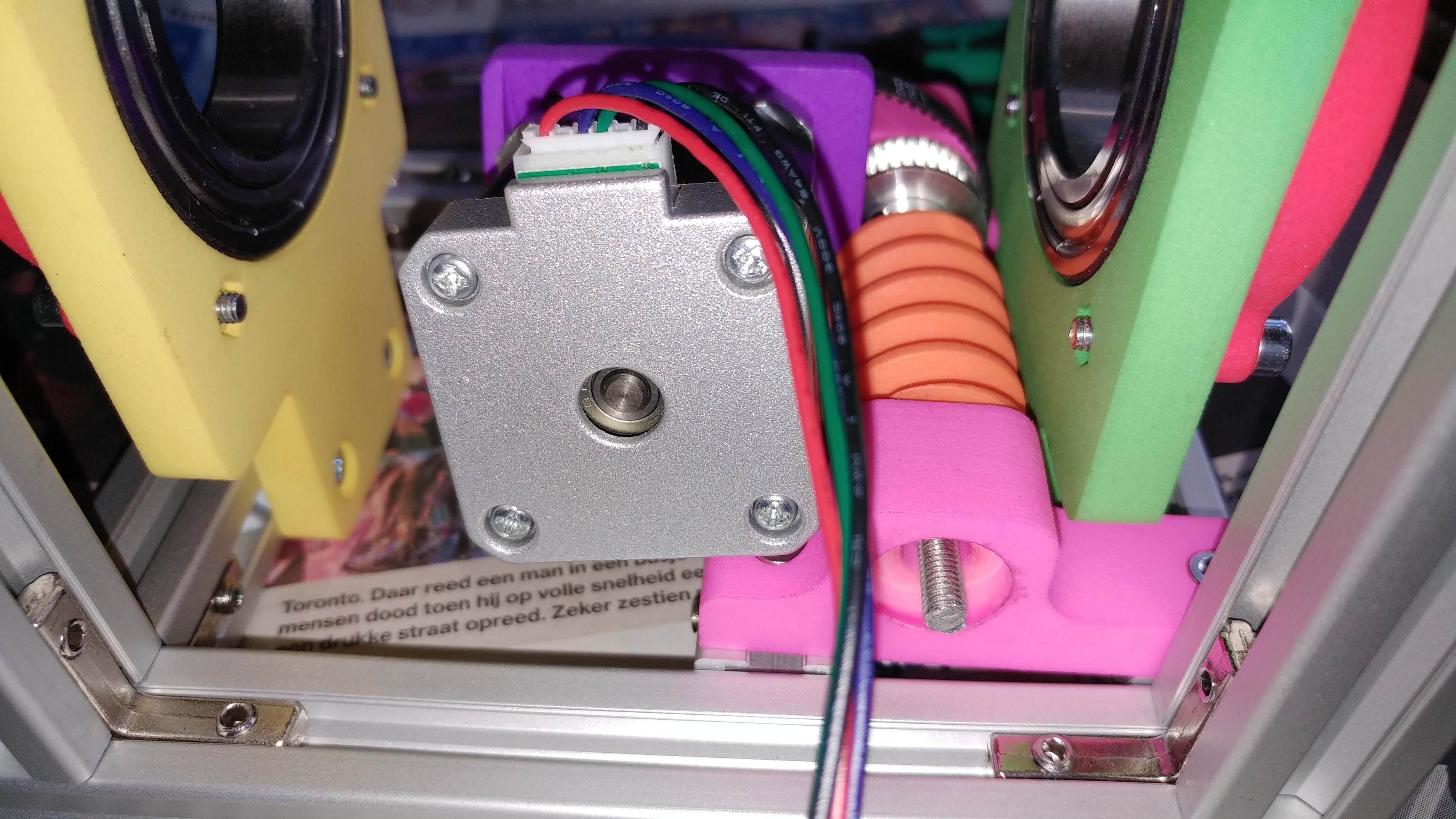
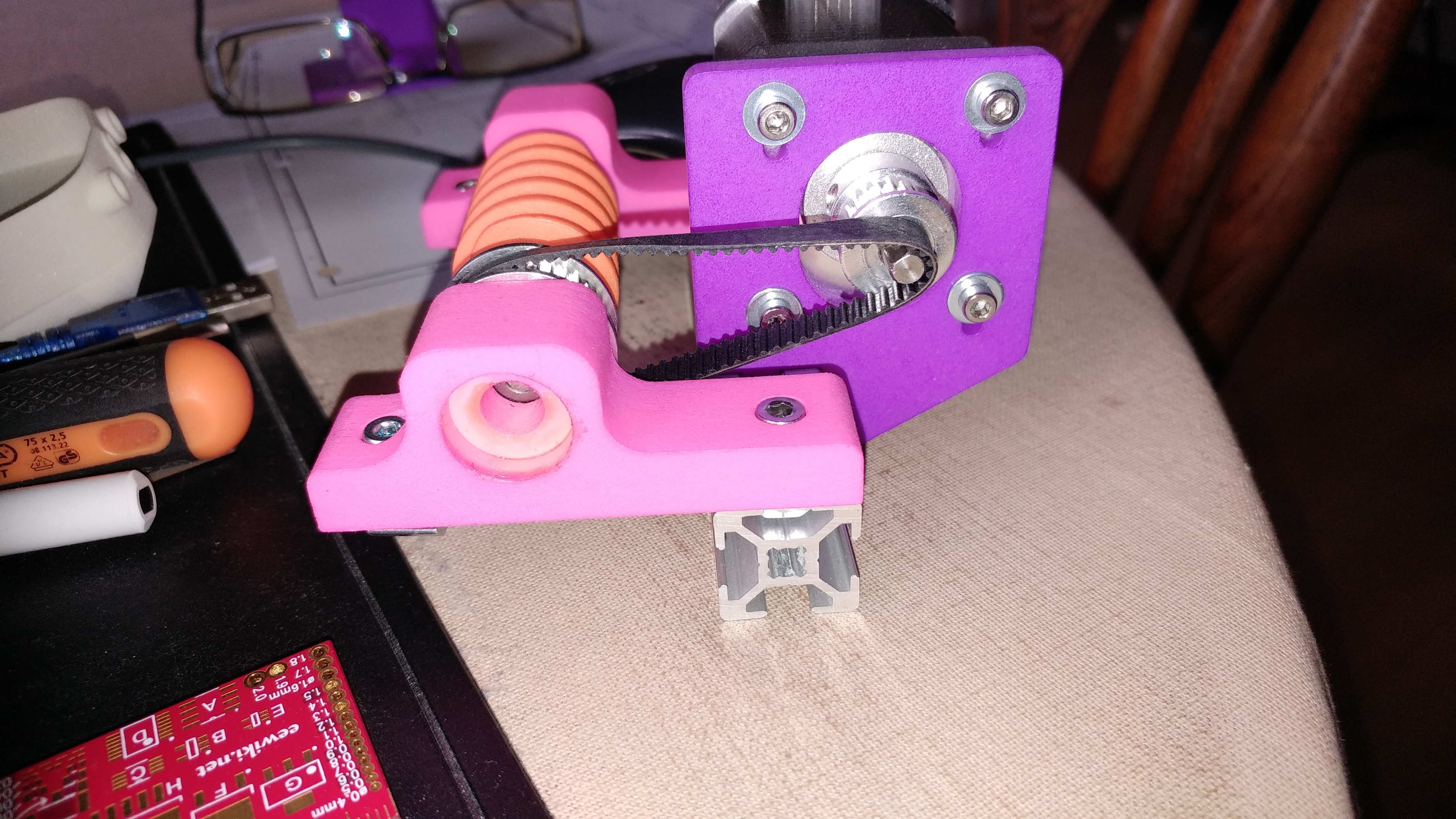
As I allready disassembled the wholw thing, I desided to rebuild only the drive part but still I cant get it right. See the pictures
It looks better but the belt wont fit
Or should i fit the belt with force, stretchn it??
Mareike
Hi All, good morning, please ignore my previous post.
Yesterday my daughter came along. She has a mechanical enginering degree… And after reading the remarks in this post, she told me to put on my classes and told me to pay morer attention on what whas written, so the two of us sat down and started over again. And after just 15 minutes I (whe) got it working. I wil post a page whit more photo’s later.
Thanks for all the help and patience
Mareike
4 Likes
Hi @berdien1955 – very glad to hear that you and your daughter got things working! I’m looking forward to seeing more pictures of your rotator.
All the best!
1 Like
It would be great if you can also fix/add any point in documentation that is confusing/doesn’t exist. Let us know if we can help with that. 
Looking good! Can’t wait to see more!
I build number two the same way. The reason for doing it this way, is that one can easyly handle the parts.
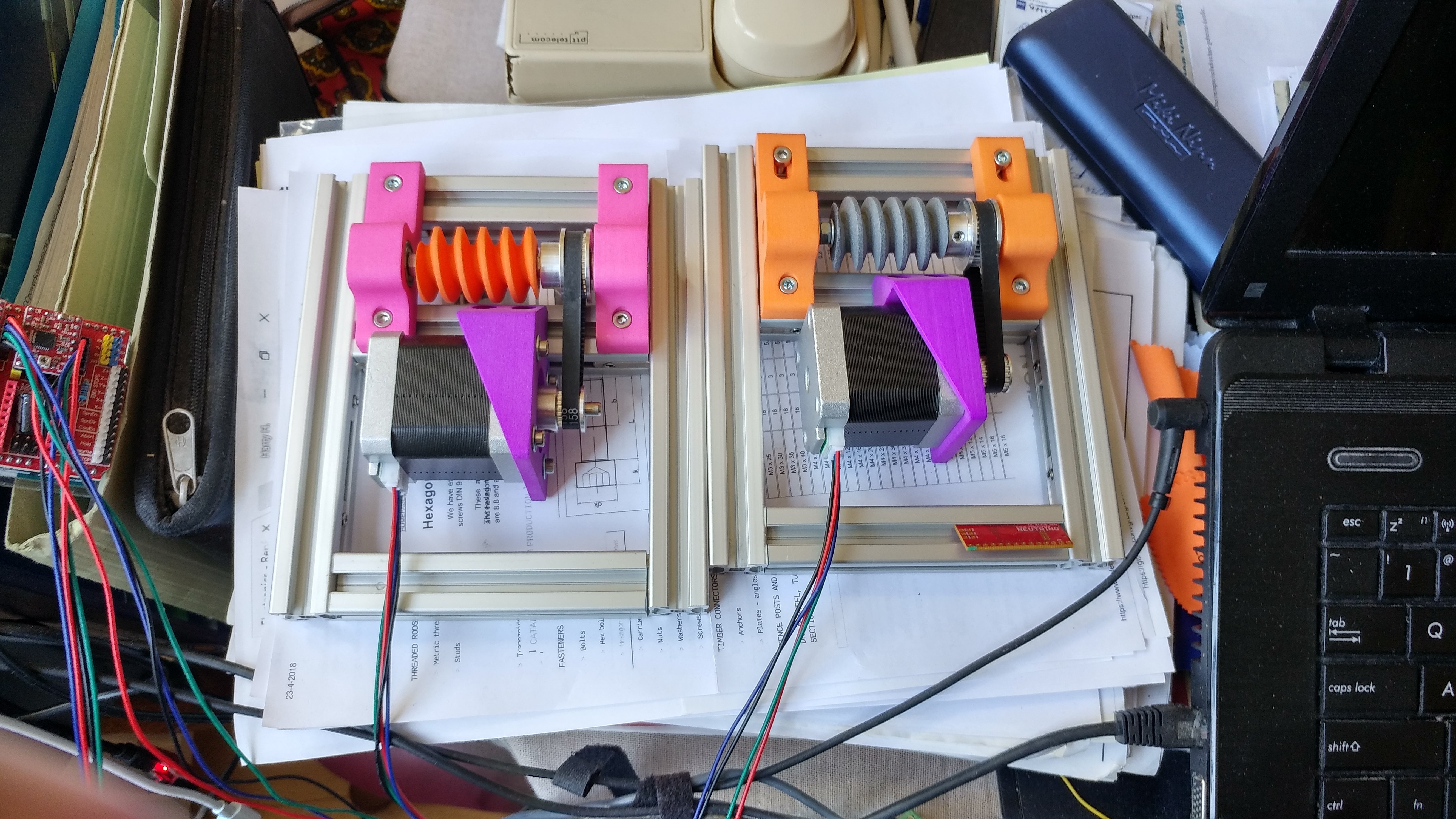
The steppers are connected by a old Arduino CNC controller for testing. The next step would be building the rset of the frame
Mareike
2 Likes
Looking good! Let us know if you run into any more issues!