My problems both ASA and PET-G bended while still printing. Main cause appears to be the fan on my Prusa printer being “allways on” which cools to much for material @ 230 degrees and 100 degrees bed temperature. Now printing in PET-G and so far so good.
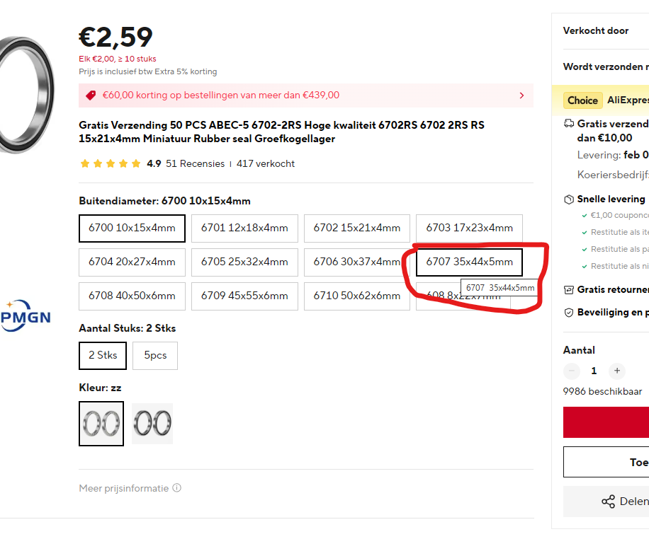
The ball bearings are named 6702-2R but with the size given ( 35 x 44 x 5 mm, which fits into tandwiel_groot) you have to choose the 6707-2x type because the 6702 is not available in that size.
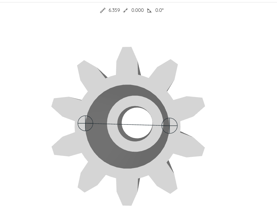
The tandwiel for the 10 turn potmeter has an inside diameter of 6.3 mm which is usefull to know if you need to buy / find these potmeters.
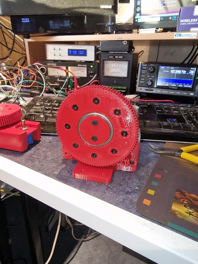
some images:
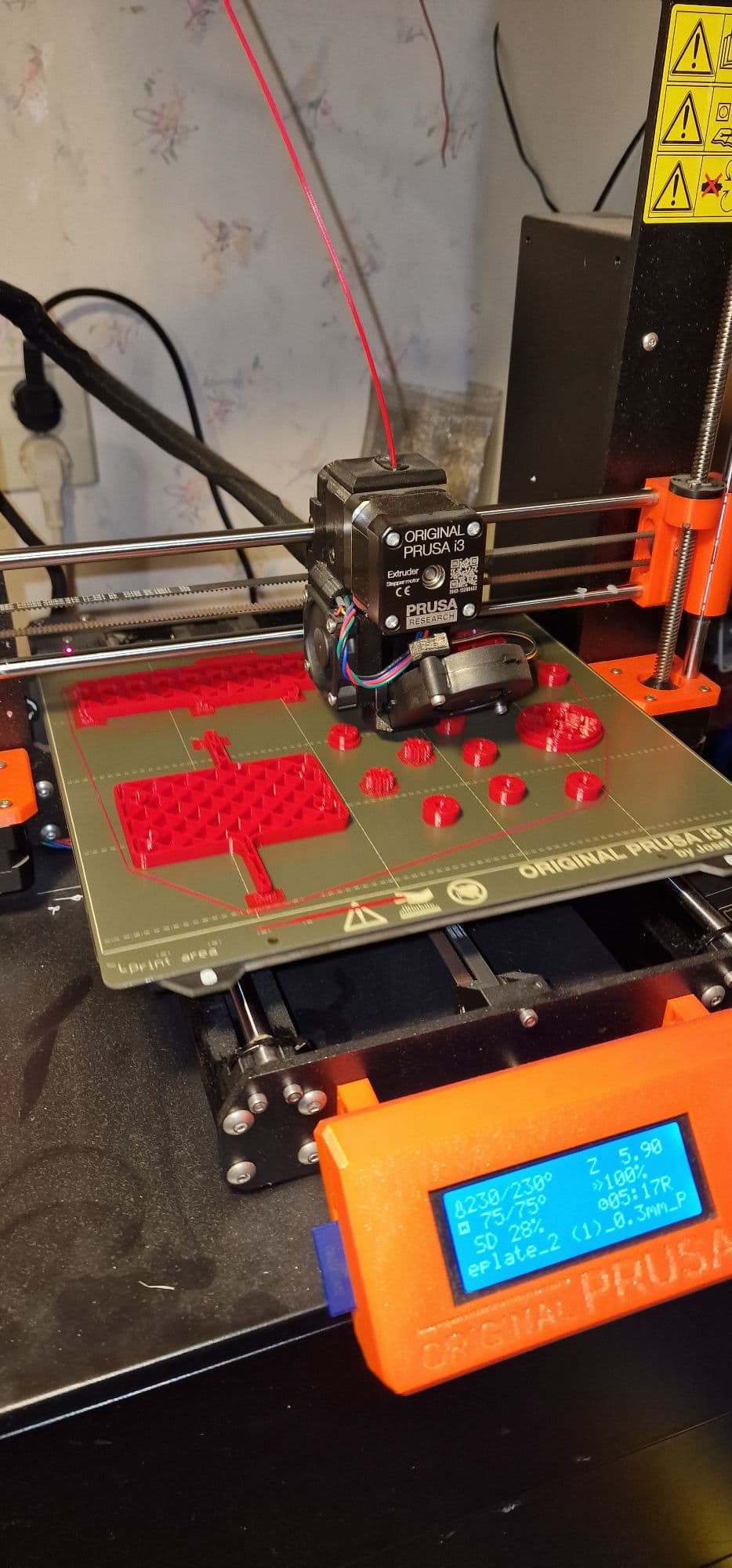
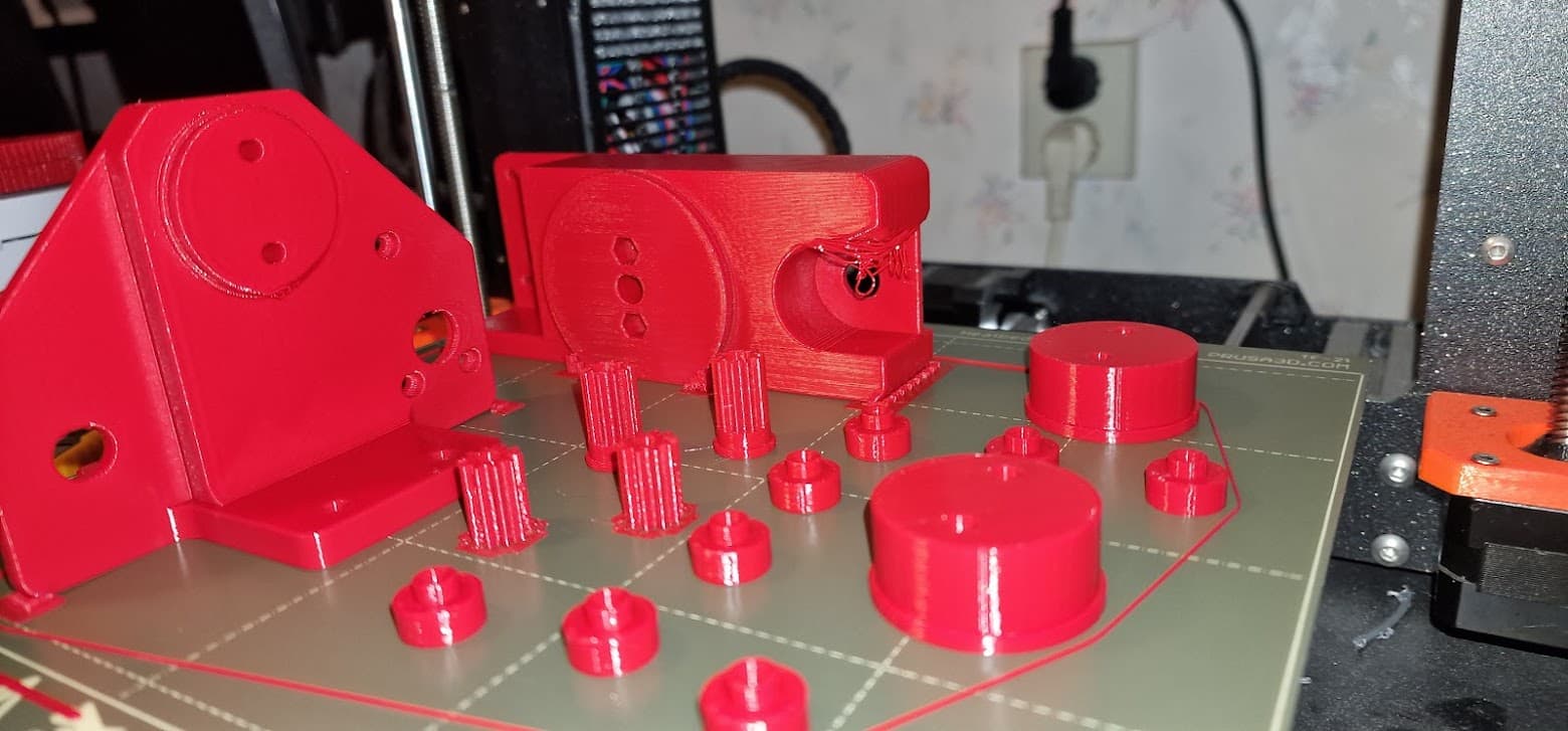
printing with the new settings for fan:
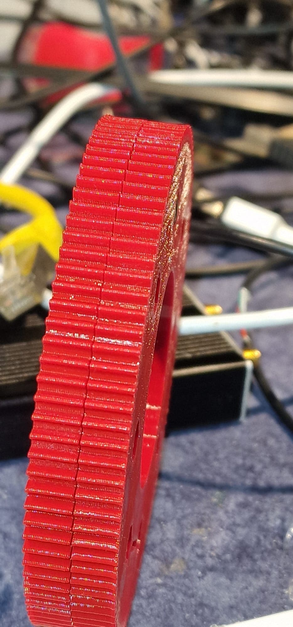
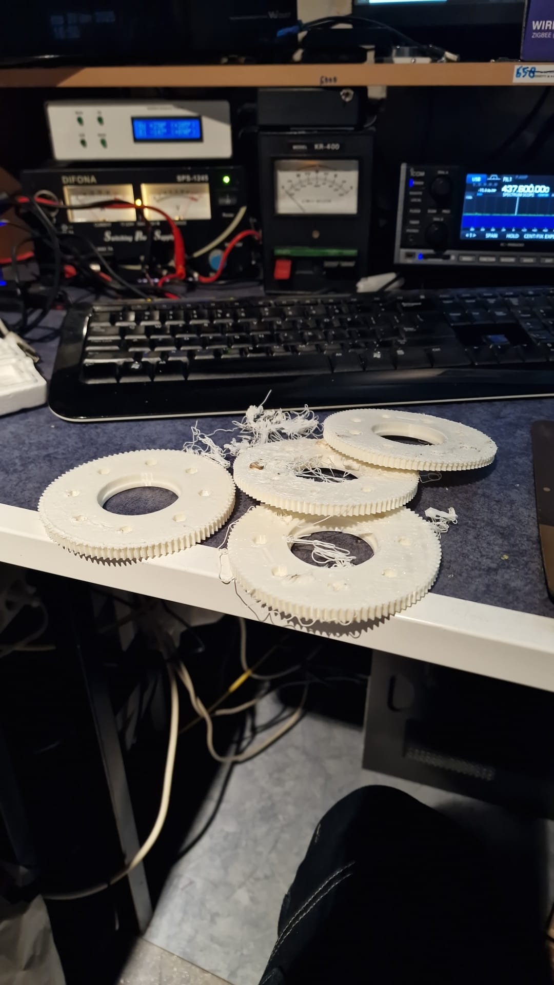
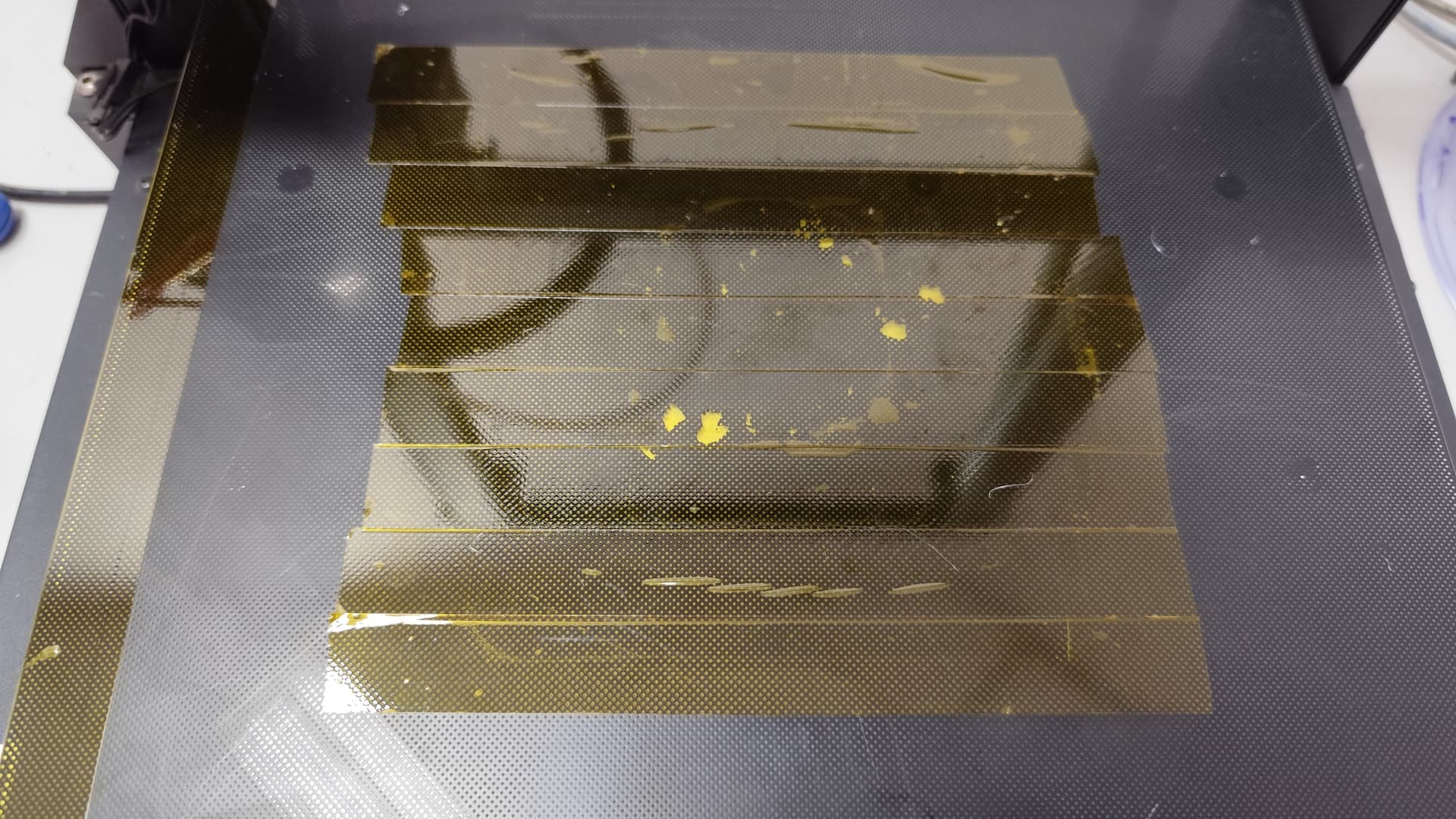
Bottom comes up from the bed while still having 20 minutes print time remaining (of 1.5 hours) which resulted in the nozzle banging into the tandwiel_groot until it came off from the bed,
Believe me, not the result you would like to see after dinner, 6 hours and 15 minutes print time:
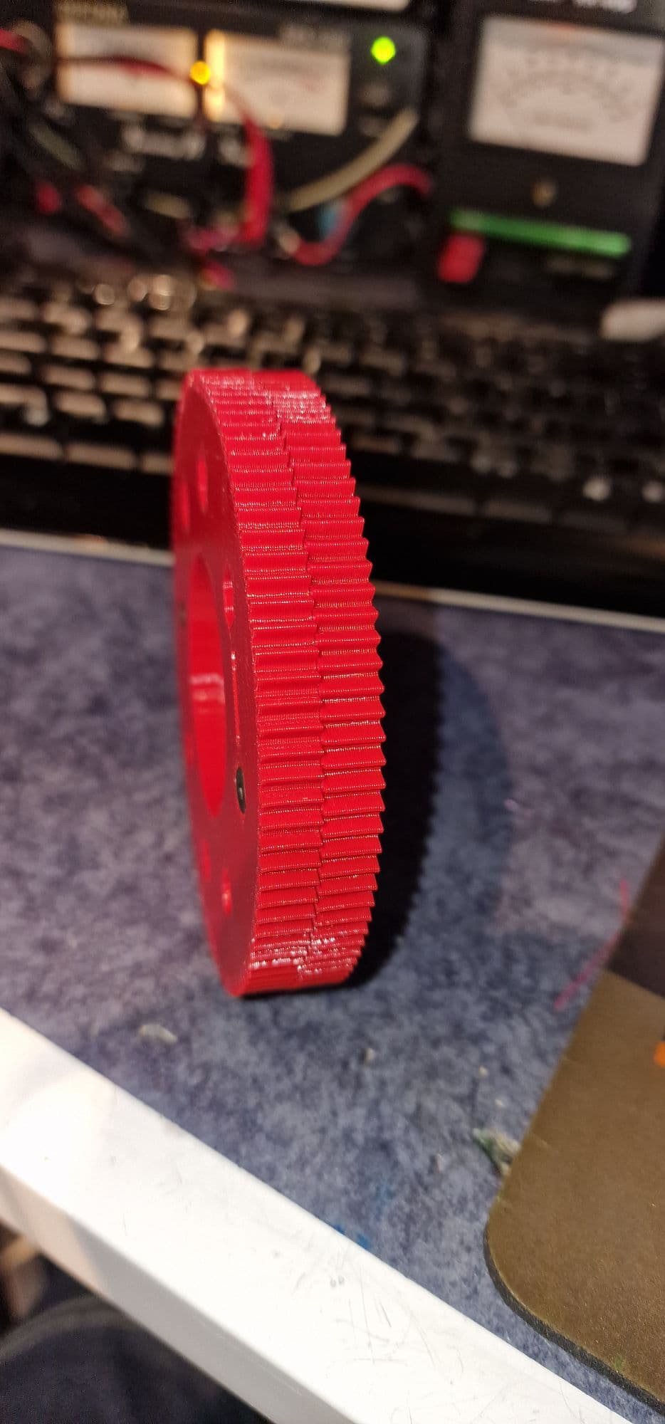
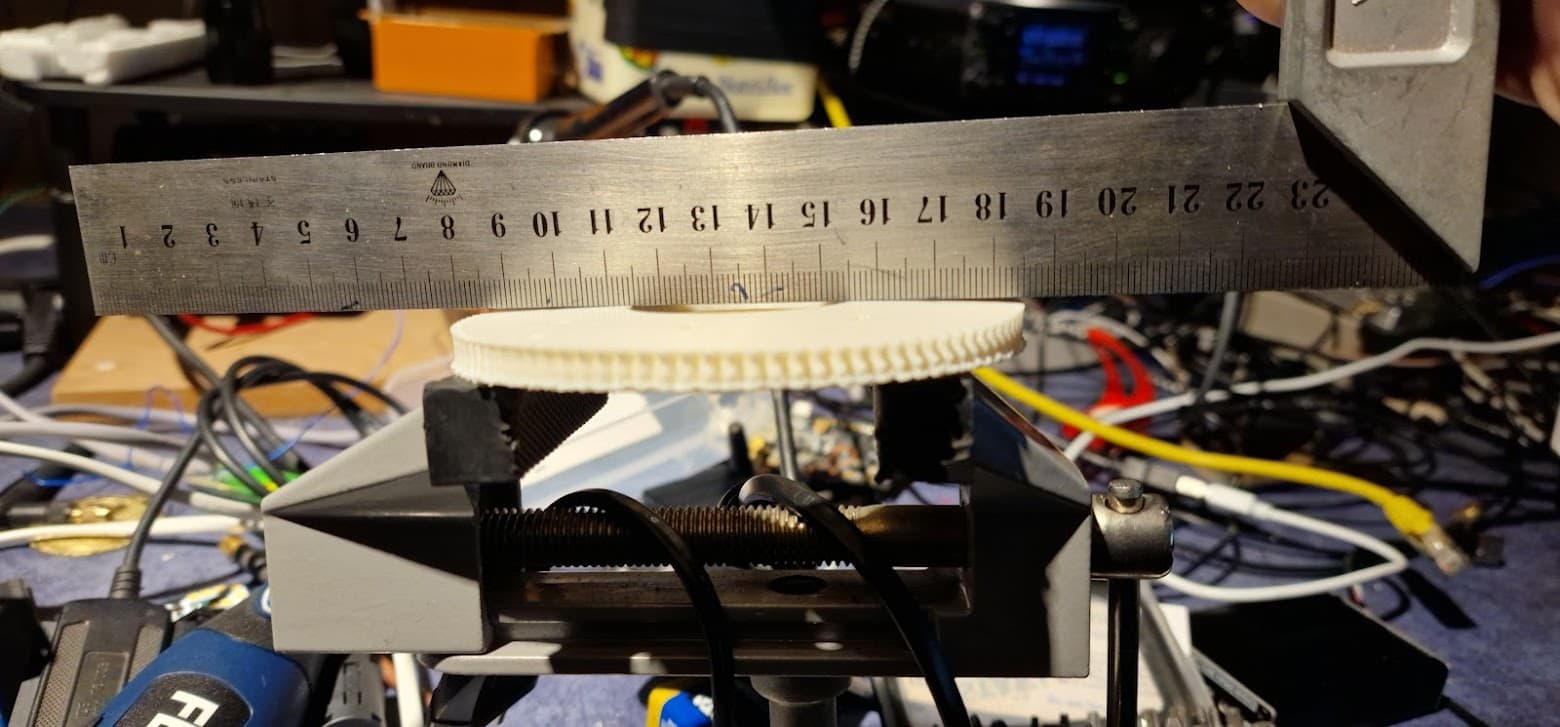
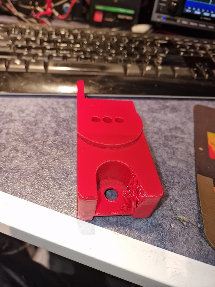
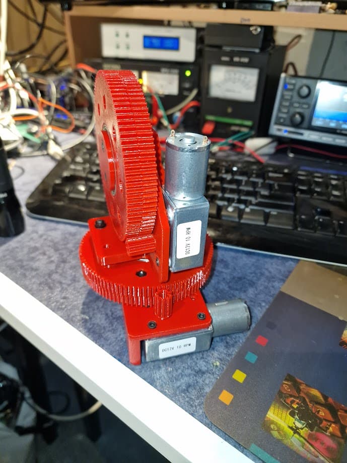
Printing finished, without (big) problems. Should have used support for one side of the base plate where a multiturn pot should find it’s place. Solved for now with a multitool and rotating sandpaper.
Wow, really nice project! I love how portable it is. Any plan for the antenna?
I think print bed layer adhesion plays an important factor on warping on my experience, I solved mine by sticking Kapton tape to the print bed. And I use the fan speed 0 at first 2 layer and 50-70% for the rest. At least it works for PLA and PETG.
Oh and by the way don’t put your printer in front of fan or AC, at least shield it in some way
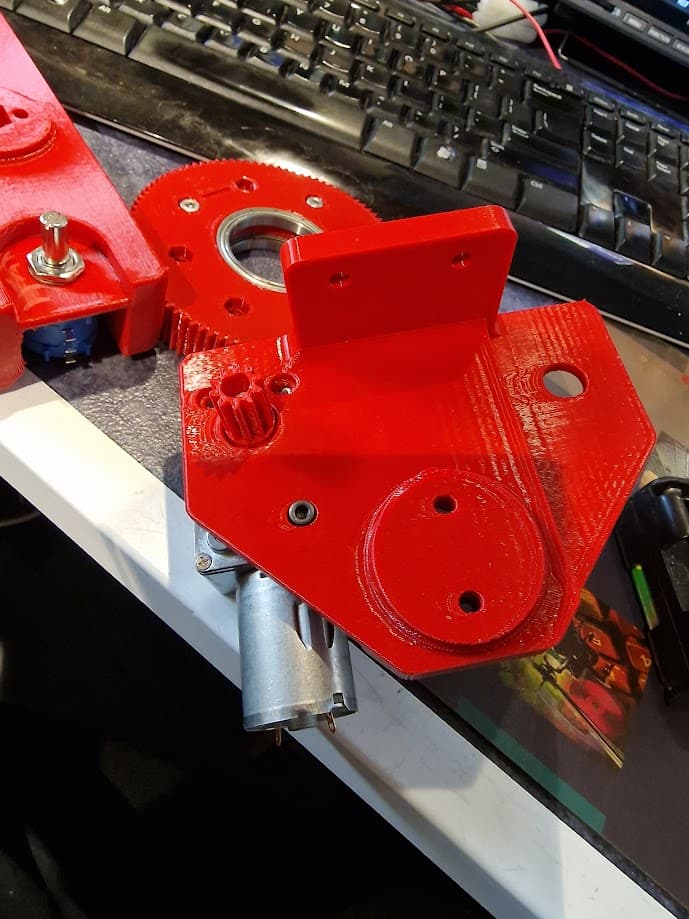
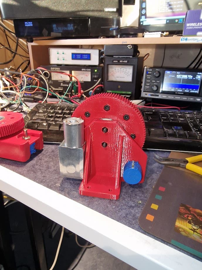
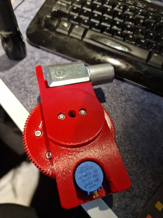
I used the plate for the potmeter below the mount to prevent the 10 turn to get dis-aligned, my potmeter has a small standing which does not pull in the hole of the plate nicely. I also placed the multiturn at half the turns before mounting it. ( 5 turns from start or end)
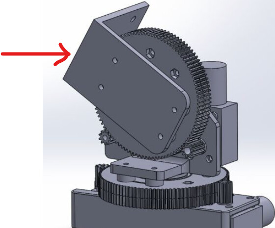
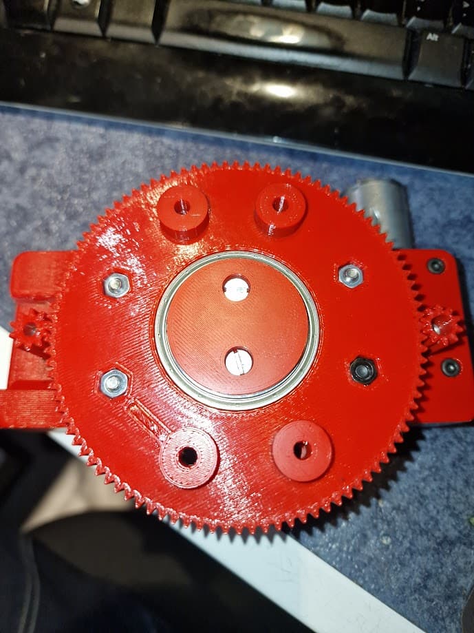
These bolts need to be about M4 x 50 mm and have to be placed before you add the spacers and mount the vertical base
Nuts fit nicely in the printed holes
4 standoffs before you add the vertical base, so if you are going to bolt the 2 large gears together you only need to use 4 nuts and bolts. the other 4 holes are being used to attach the vertical base to the 2 large gears.
Remeber you have to apply some DC to the motor to rotate the big gears to get access to the holes for mounting the vertical base. Make sure your multiturns do not start in an end position !
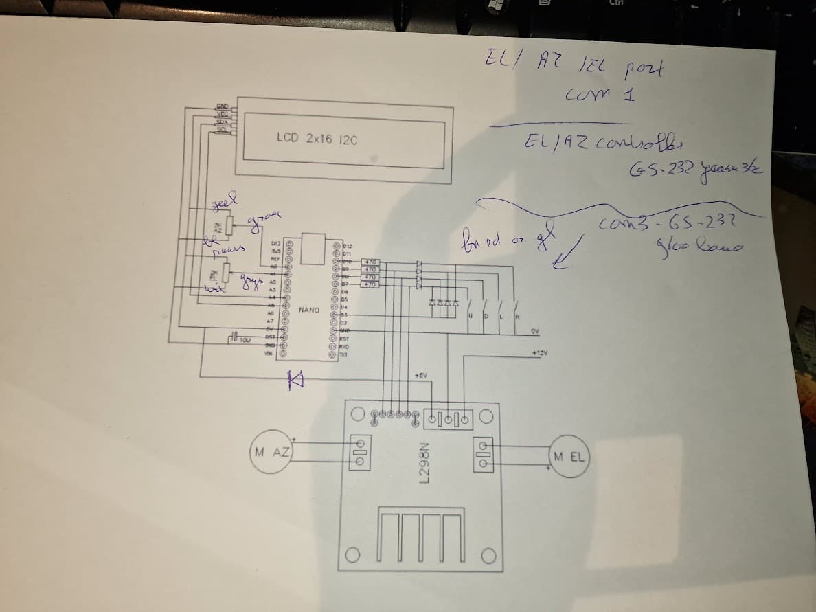
Finished the arduino programming, and wiring, and started to test. Potmeters can run from 0 to 360 degrees (Azimuth) but the line 98 in the software is set for 450 degrees, which makes the rotor run into the mechanical limit of the multiturn. Now going to try with the setting on 355 degrees.
const long _maxRotorAzimuth = 35500L; // maximum rotor azimuth in degrees * 100
I recommend to use an 1N4001 - 4007 between the +5 v output of the motor controller and the 5v Input of the arduino nano.
If you run into an error and disconnect the +12 V DC from the motor controller the motors continue to turn slowly, powered from the +5 V from the USB port
Especially the difference between rotorMoveAz - rotorMoveAz -180; for if move >180 degrees and the line rotorMoveAz = rotorMoveAz + 18000; for if move < -180 degrees
I cannot yet figure out which one to change. Anyone with a flashlight to shine a light on this ?
I would like to thinkk that the -180 should be replaced by -18000
There seems to be a typo in line 11 , 180 vs 180000
In general: What are the intended units? It seems that rotorMoveAz is given in 1/1000th of a degree, while the azRotorMovement output string is returning 1/10th of a degree, is this intentional?
Off-topic: Further discussion of this code could really benefit from hosting it in some code forge, e.g. gitlab.
  SimpleSat Rotor Control Program  -  73 de W9KE Tom Doyle
  January 2012

  modified by pe1ckk for plane scatter 24G printed rotator

  Written for Arduino 1.0

  This program was written for the Arduino nano boards.
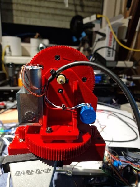
Tonight I decided to disconnect the flat wires for the rotating part of the motor / potmeter and replace is by one cable. Created some sort of portection so the wires do not get pulled from the motor and potmeter.
Now testing code modification with help from PD7R, who explains what he think the code is ment to do, (deciding if either left or right rotation is the shortes way to the needed azimuth) and go that way. Paste code below for reference, now going to flash and test.
The bad news is, that did not work, at first, but now I have exchanged Azimuth motor V+ and V- , so now, if I set PST rotator at a lower AZ as the potmeter it turns in the right direction, and if I set is to a higher AZ it turns also in the right direction and stops at the moment it supposed to stop.
last update for now:
Azimuth problem indeed solved with the software changes and reverting the AZ motor + and -.
After testing I found no way to mount an antenna following the correct elevation, I noticed that motor was running in the unexpected direction too. Changing + and - for the EL motor solved the direction, but the multiturn potmeter now decreased value at increasing elevation so I exchanged the two outer wires for the EL potmeter too. Manually set the elevation at 90 degrees, and, without the small gear installed, set the multiturn to 90 degrees EL value, re-attached the small gear and controlling the elevation now matches the multiturn value.