Superb! Can you explain the 200 Hz jump? Is that DSN switch over? Is there also an unlocked carrier in between sessions?
Very nice result! ![]()
Superb! Can you explain the 200 Hz jump? Is that DSN switch over? Is there also an unlocked carrier in between sessions?
Very nice result! ![]()
Yes, that’s DSN switchover from Canberra to Madrid.
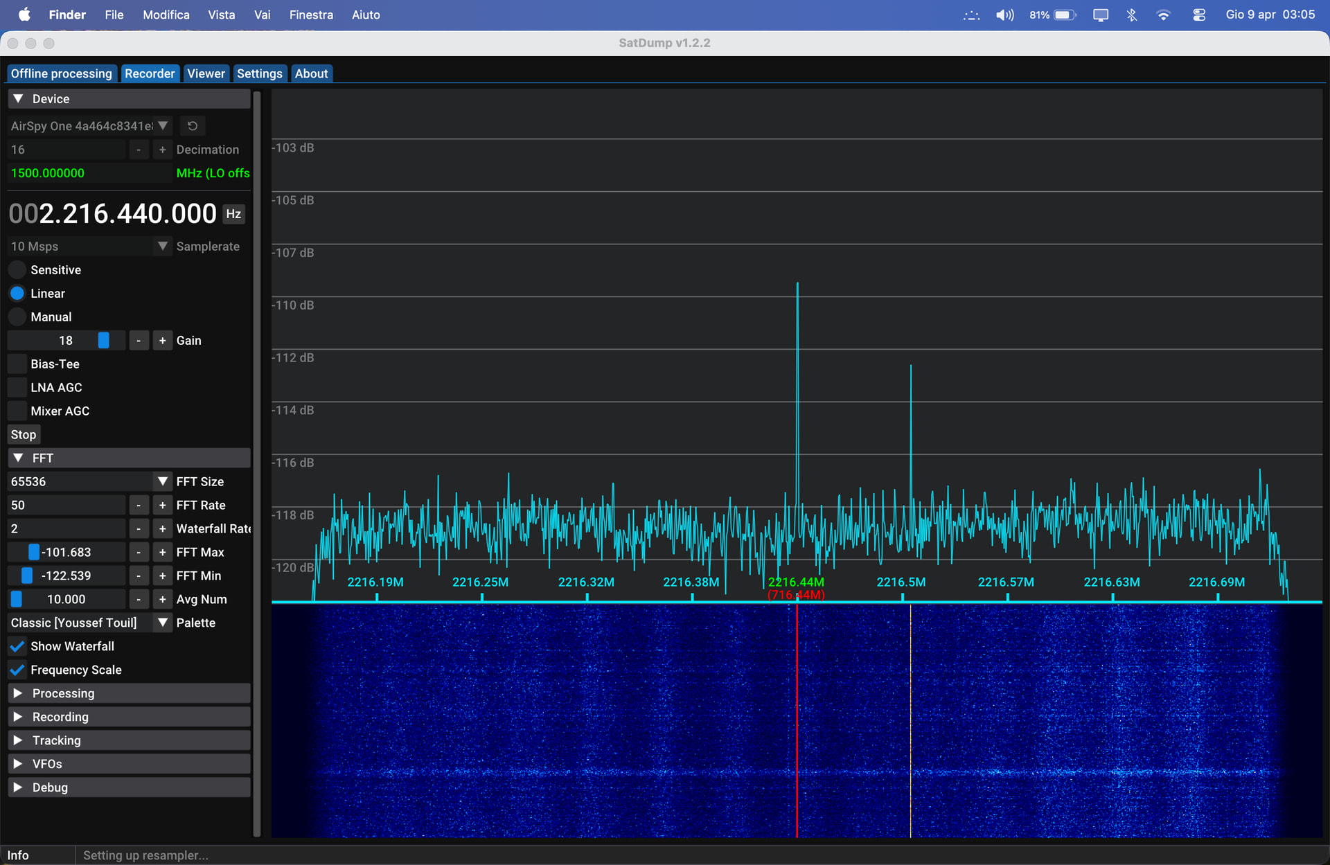
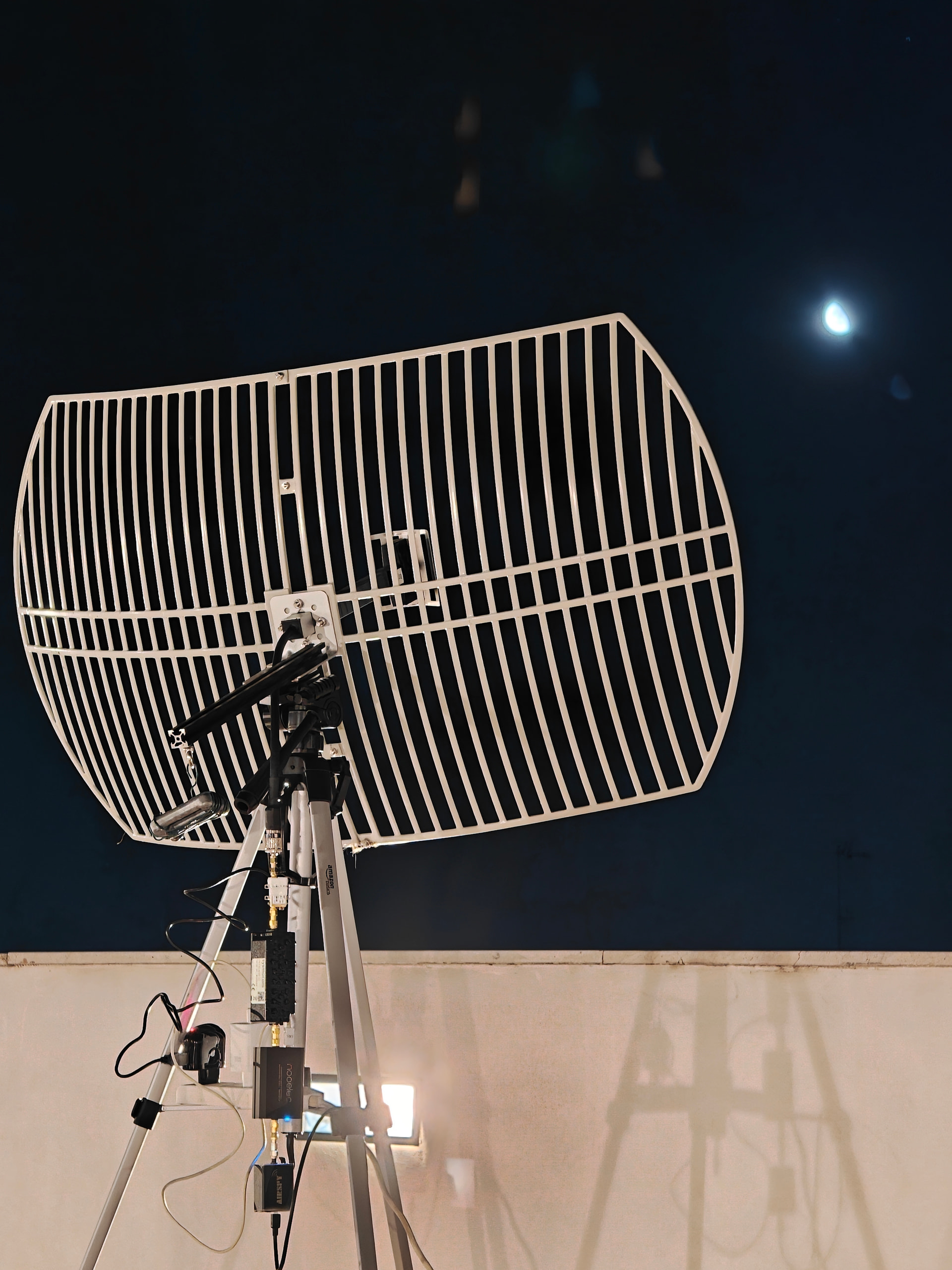
Hi all, I’m Simone and it’s my first time here but I really wanted to share my results. I read this forum a lot and you’ve really been an inspiration to me. I’ve been able to track Artemis 2 on the last nights (yesterday and the night before). I wrote all the details here GitHub - solletichino999/artemis2 · GitHub
thank you my friend. nice and clean setup. i put your photo here for archieve:
System used:

    80 cm 2.4 GHz Wi-Fi grid dish (23.3 dB at 2.2 GHz) with stock linear dipole feed (-3 dB with Orion RHCP)
    Mini-Circuits ZX60-242GLN-S+ LNA powered via USB
    Sysmocom S-Band cavity filter (2170-2300 MHz)
    Nooelec Ham It Down downconverter powered by USB (1500 MHz LO)
    Airspy R2 in linear mode with 16x decimation
    MacBook Air M4 with SatDump running
    AmazonBasics lightweight camera tripod
    Custom dish-tripod adapter with diving counterweight (designed by ChatGPT)

An AntRunner rotator was available but wasn't used since Orion was moving slowly in the sky, the dish had 11° beamwidth (at -3 dB) and was manually oriented every ten minutes with the help of an Android smartphone. A Leo Bodnar LBE-1420 GPSDO was available but wasn't used because precise Doppler measurement was out of scope. Pointing was done using the attached Jupyter notebook (made with the help of Claude Code), which took the updated data from JPL Horizons. Time in the screenshots and in file names is UTC+2.
my wishlist:
Nooelec Ham It Down downconverter powered by USB (1500 MHz LO)
73!
bali
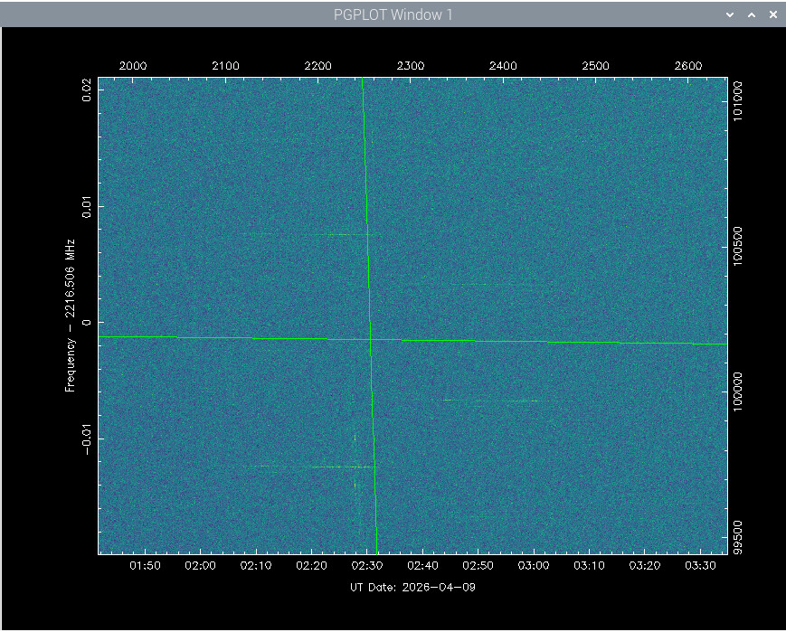
Last night the elevation of Artemis II was only 5 degrees for me. It was only visible in between two houses, from 2 to 3 UTC, checking the pointing on JPL. Unfortunately, the strong carrier had just stopped before it came into my view, according the Amsat live stream. But they are getting closer to earth, and the signal strength is getting high enough to show the data harmonics:
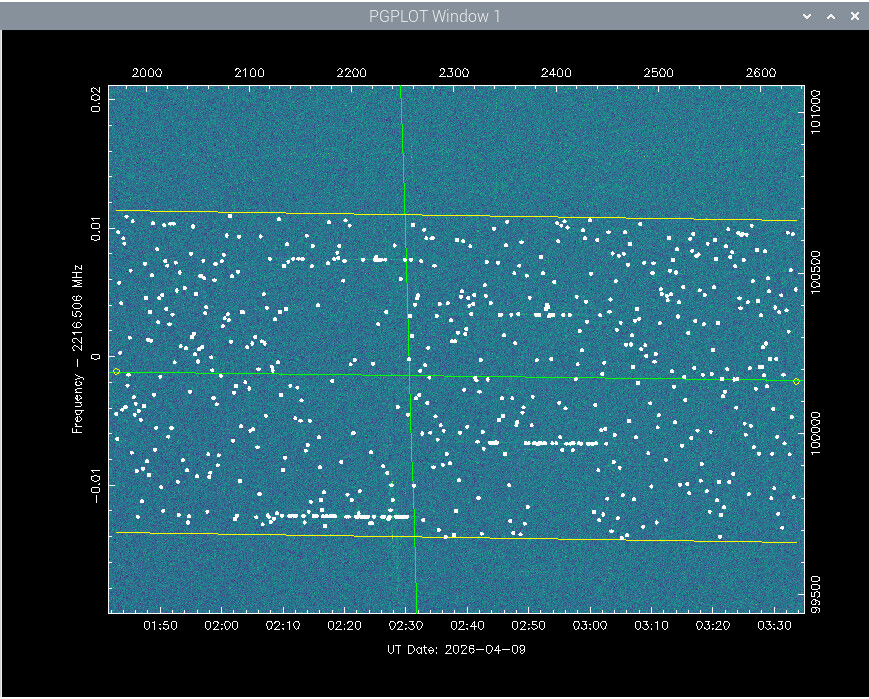
Here are 4 lines visible. Using the detection it shows the lines and a lot of noise:
Cleaning the noise gives:
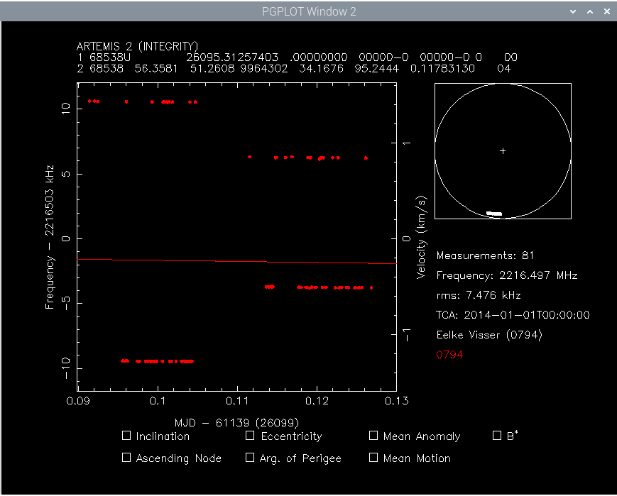
I have fitted each of the four lines and noticed the left lines are 20kHz apart and the right lines are 10kHz apart. Left:
68538 2216.508957 0.016 2014-01-01T00:00:00 0794 26095.312574
68538 2216.488956 0.018 2014-01-01T00:00:00 0794 26095.312574
Right:
68538 2216.494827 0.020 2014-01-01T00:00:00 0794 26095.312574
68538 2216.504817 0.036 2014-01-01T00:00:00 0794 26095.312574
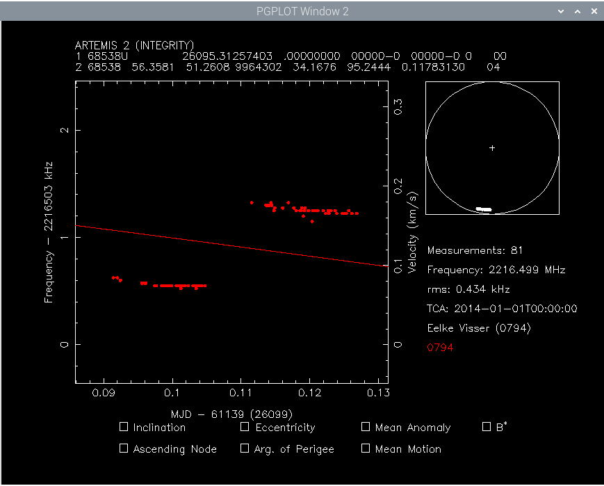
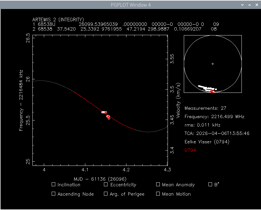
I decided to move the lines a 10 and 5 kHz, to get them to align as a single carrier. This results in 2 groups, each has a very low rms error with respect to the old TLE. But it shows a rms error of 434 Hz, and a large gap between the two groups:
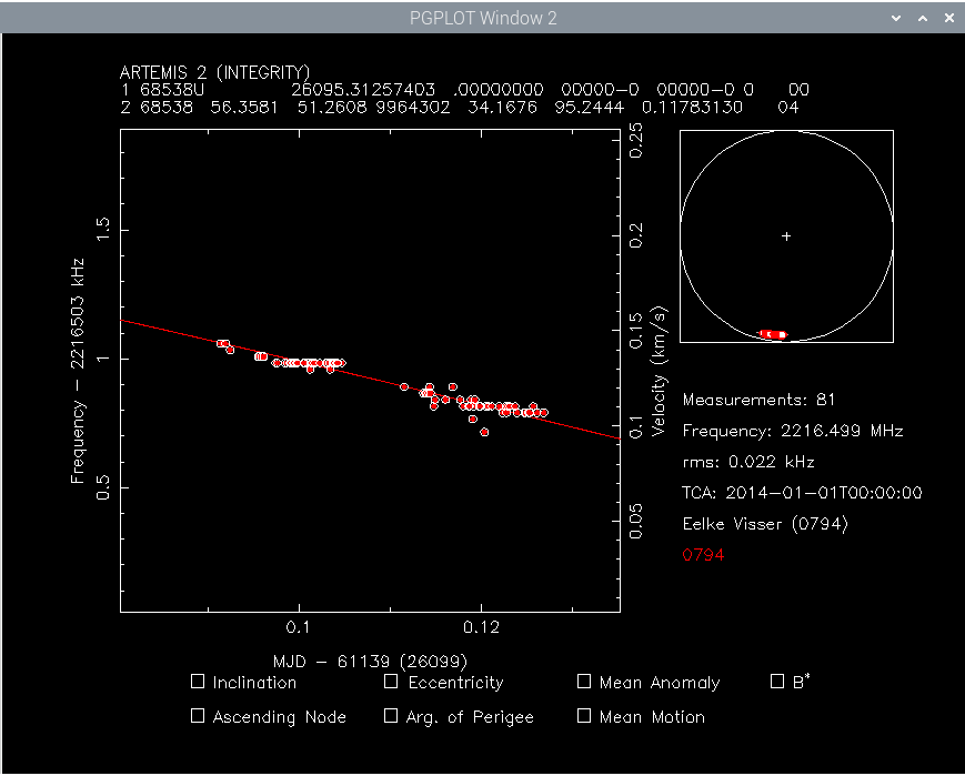
That is not satisfying. And very unscientifically, I moved them by 434 Hz and finally I got a nice curve:
The rms is low, but moving points around is not desirable, but sometimes you must work with what you get. I am already surprised that I have recieved it a lot more then expected!
Thank you for posting the other photo, as a new user the system won’t let me attach more than one photo in a post. The ham it down is a very good piece of hardware, especially if you don’t have an s-band capable sdr such as the bladerf or the limesdr.
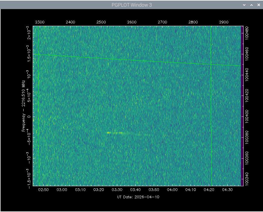
The Artemis II mission is about to come to a finish. Splashdown of the spacecraft is expected tonight. Last night was the last chance for me to observe it. I didn’t expect to receive it as the elevation was only 2.5 degrees. But surprisingly I got a streak starting 03:25, which matches a mode change according the Amsat live stream.
Space Track has issued several TLEs, and using the latest shows a good match:
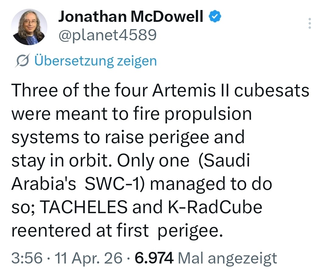
This almost concludes the Artemis II mission. Only thing left is to look for the SWC-1 cubesat that was on this mission too. It had raised its perigee and is still in orbit. Space Track has updated its TLE, see 68540. Frequency is expected at 2251.7 MHz.
I looked at SWC-1 last night, but didn’t receive it. This doesn’t mean much for it’s status, as my dish might be just too small, or it is not transmitting continuously.
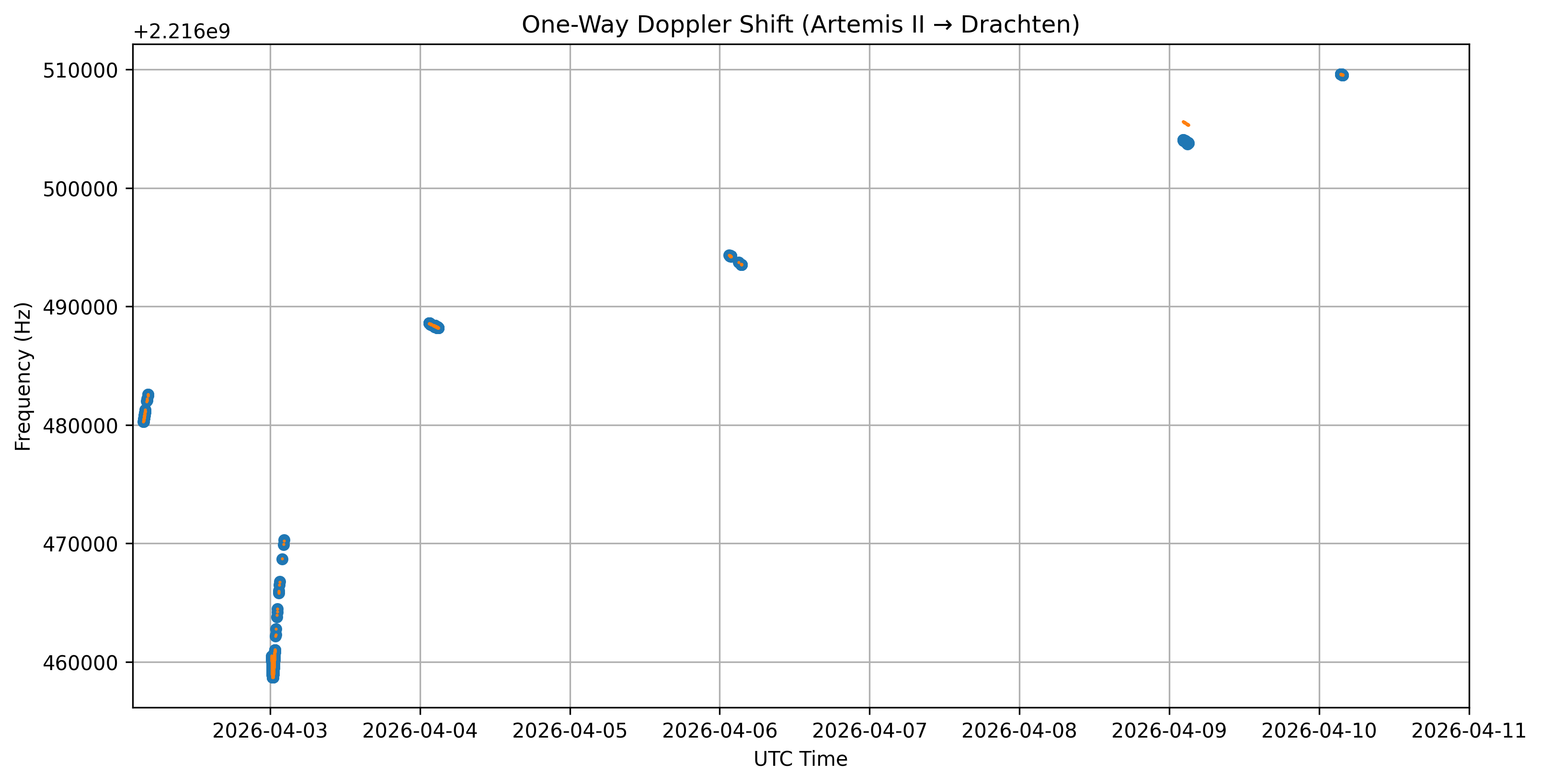
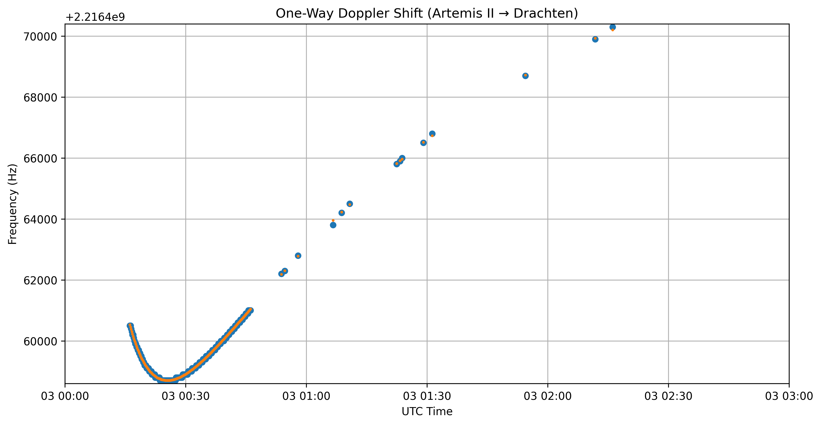
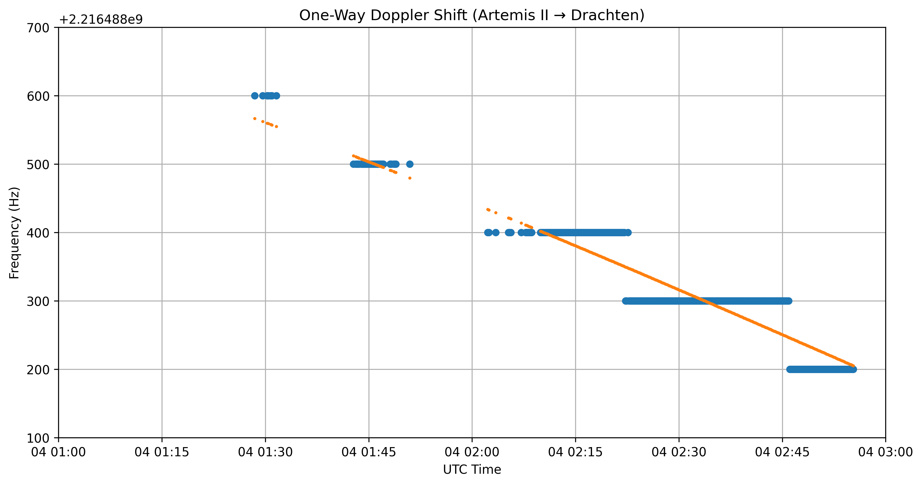
I had finally some time make the plots of the received Dopppler vs the expected range rate based Doppler of JPL. I had used frequency bins of 100 or 50Hz, which limits the resolution. I have a applied a constant offset of 1880 Hz to all plots, to make it fit nice.
Over all:
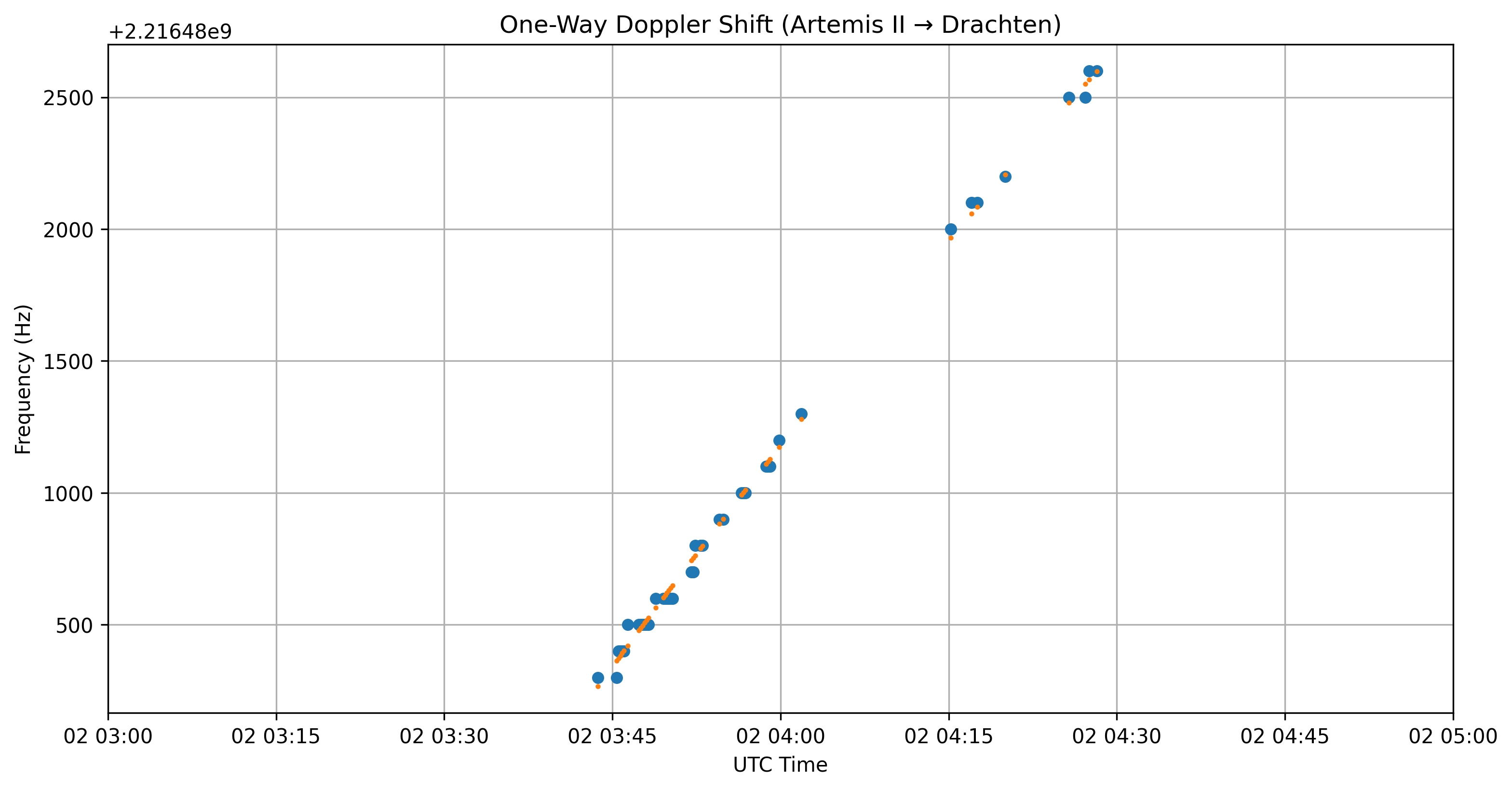
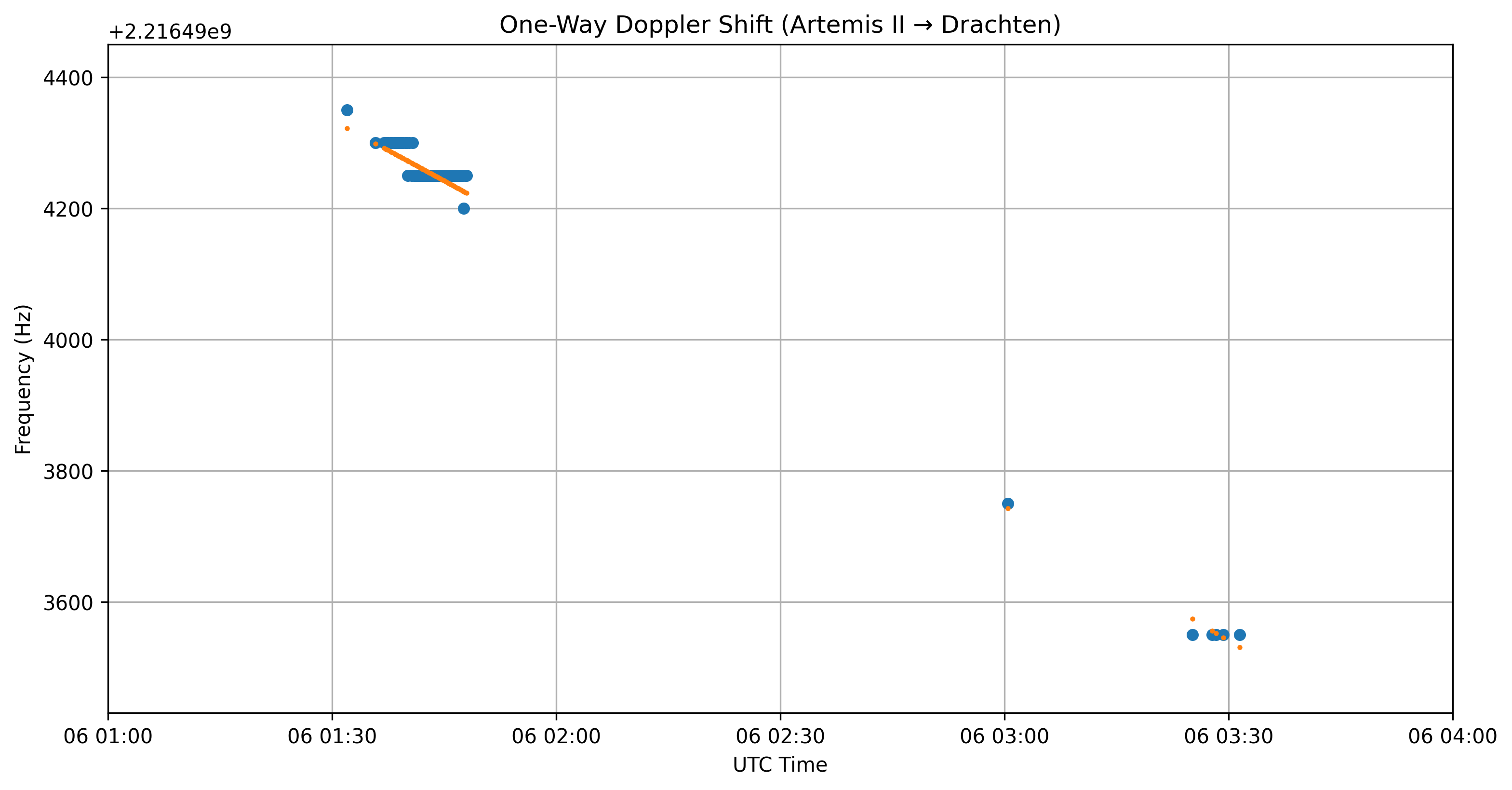
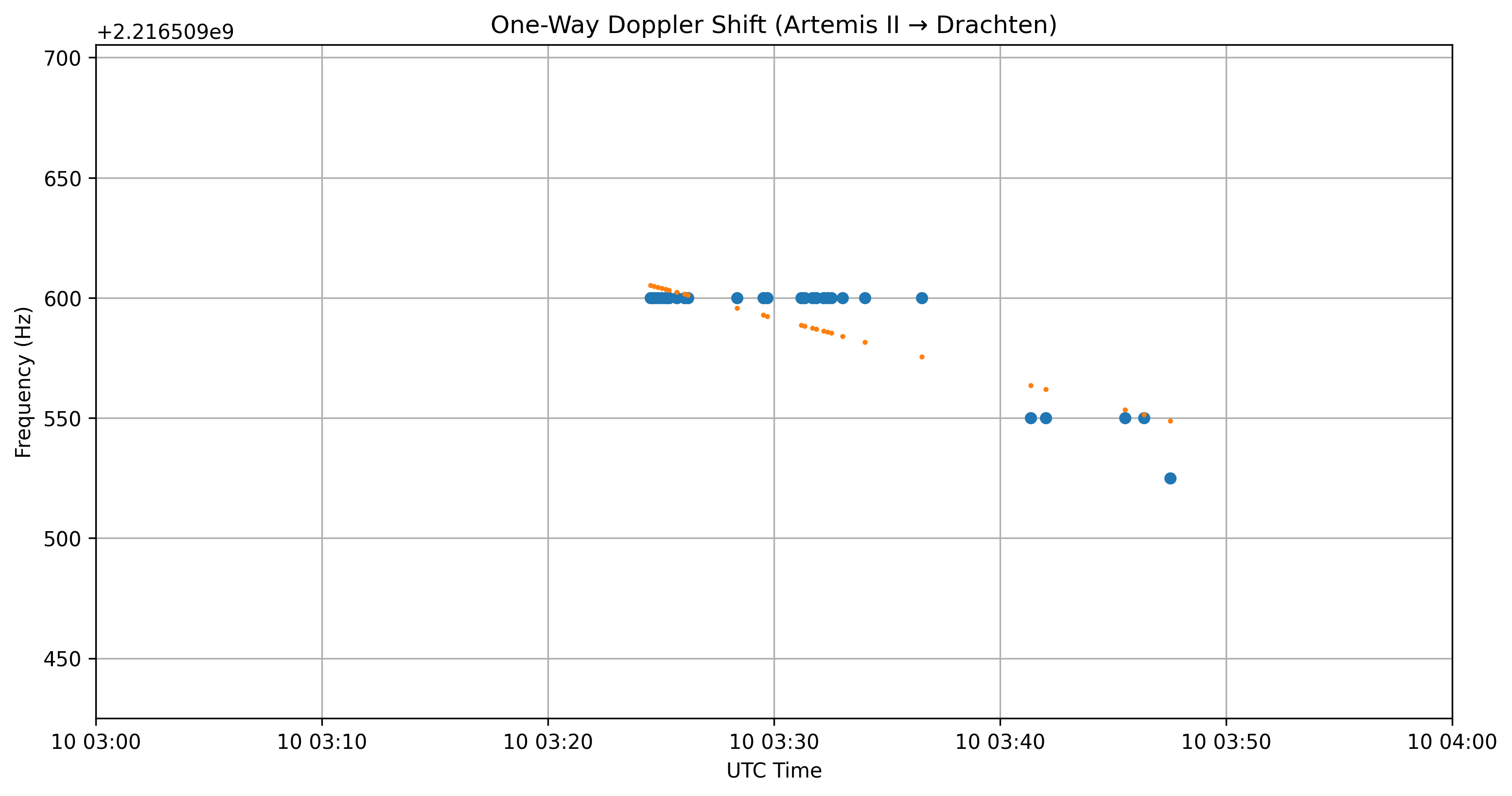
Zoom in on the data:
As can be seen I used some side band carriers of the 9th of April, and the frequency was a bit off. The rest of the data fits very nice!! ![]()
Thanks for sharing - very interesting!
I’m way out of my knowledge zone to even ask this, but do you think the expected doppler differences w/ the wide-band downlinks were because when in that mode it was more likely locked to a ground station uplink? (which throws a wrench into straight math calculations)
Good questions! I think it was (almost) always ground locked. That makes sense as the transmitting ground station is in control of the frequency and that can be determined much more accurate on Earth than by the spacecraft itself.
I have been trying a two way Doppler in rffit, but didn’t get any good results. Therefore I concluded that it is not a two way Doppler where the transmitting ground station uses a constant frequency and we have to calculate the Doppler twice.
It is currently also being discussed in the Artemis II elements chat: “piecewise linear ramping of the uplink is quite clear in our data as well.” I assume the transmitting ground station uses a frequency that is already Doppler compensated. The Artemis spacecraft receives a constant frequency and we see only the return path Doppler.
I am also learning this stuff while doing it. It’s just my two cents!