As part of an experiment we have to build 4 antennas with quite wide beamwidth suitable for satellite signal reception with no mechanical tracking mechanism.
Quadrifilar helix are one of the best candidates for this particular job. So far so good. We started building the antennas for the 433 MHz band, just to discover that it is very difficult to make them to have the same characteristics. Especially in this band, tiny offsets from the “proper” values affect greatly the performance of the antenna. Also due to the size of the antenna, it was quite difficult to put support tubes, leading to mis-alignment due to inconsistent wire bending.
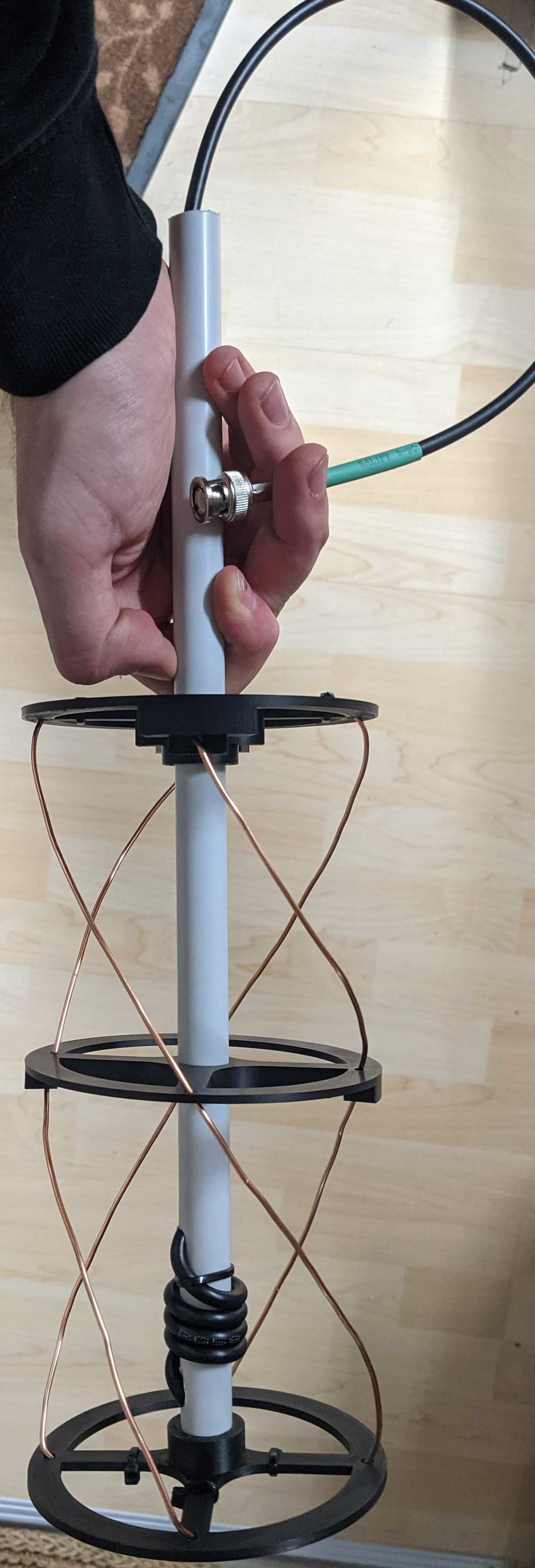
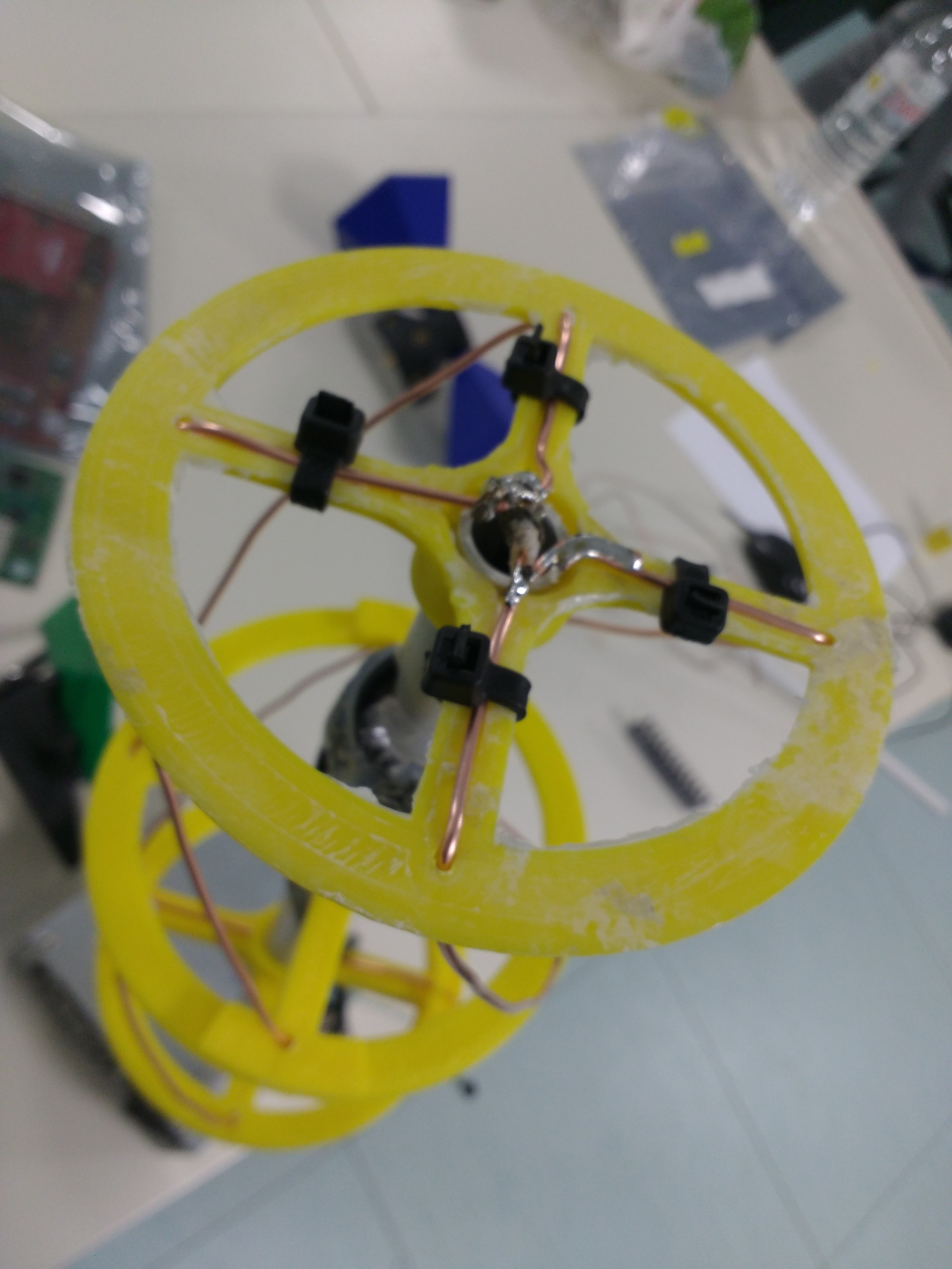
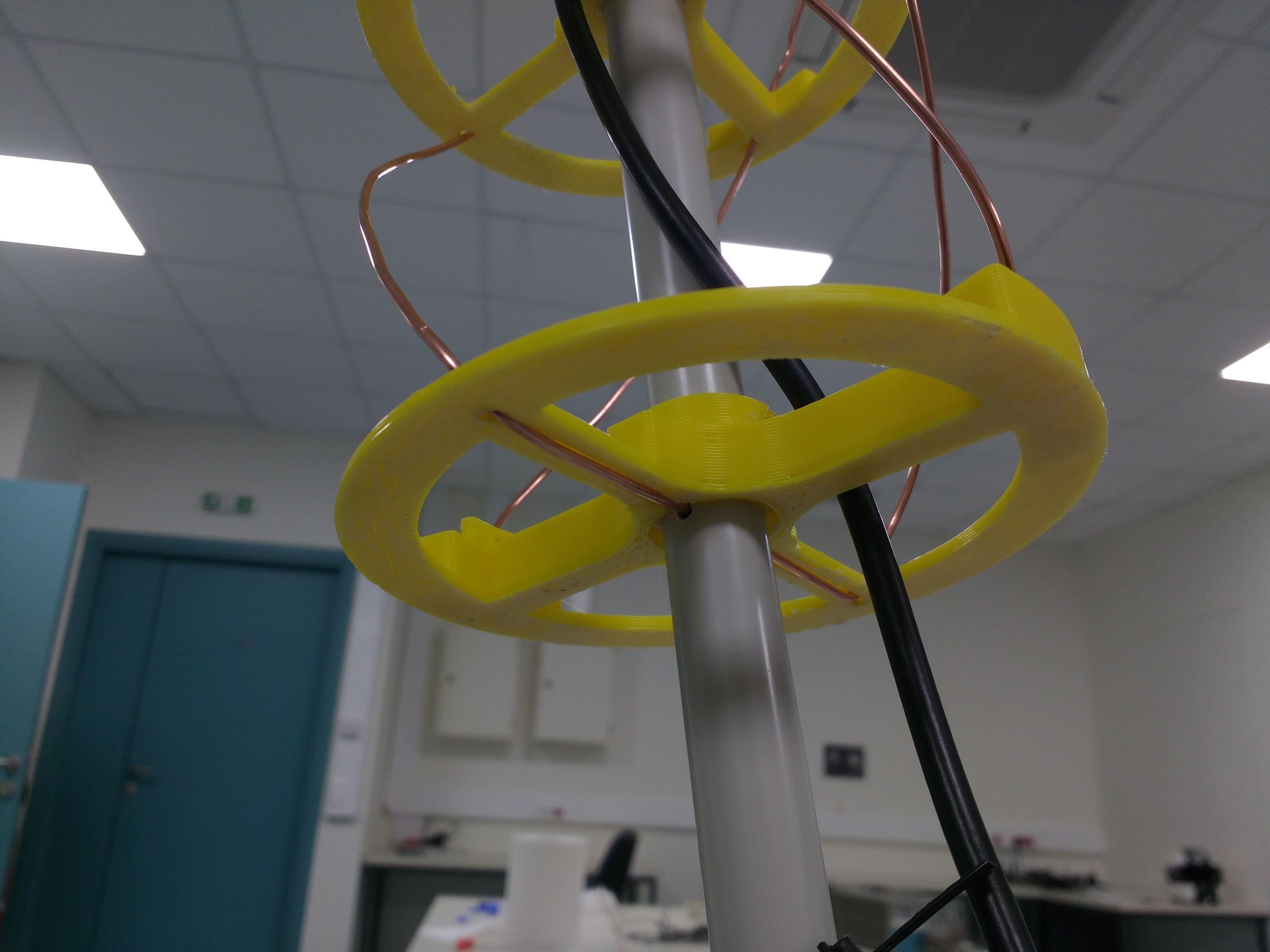
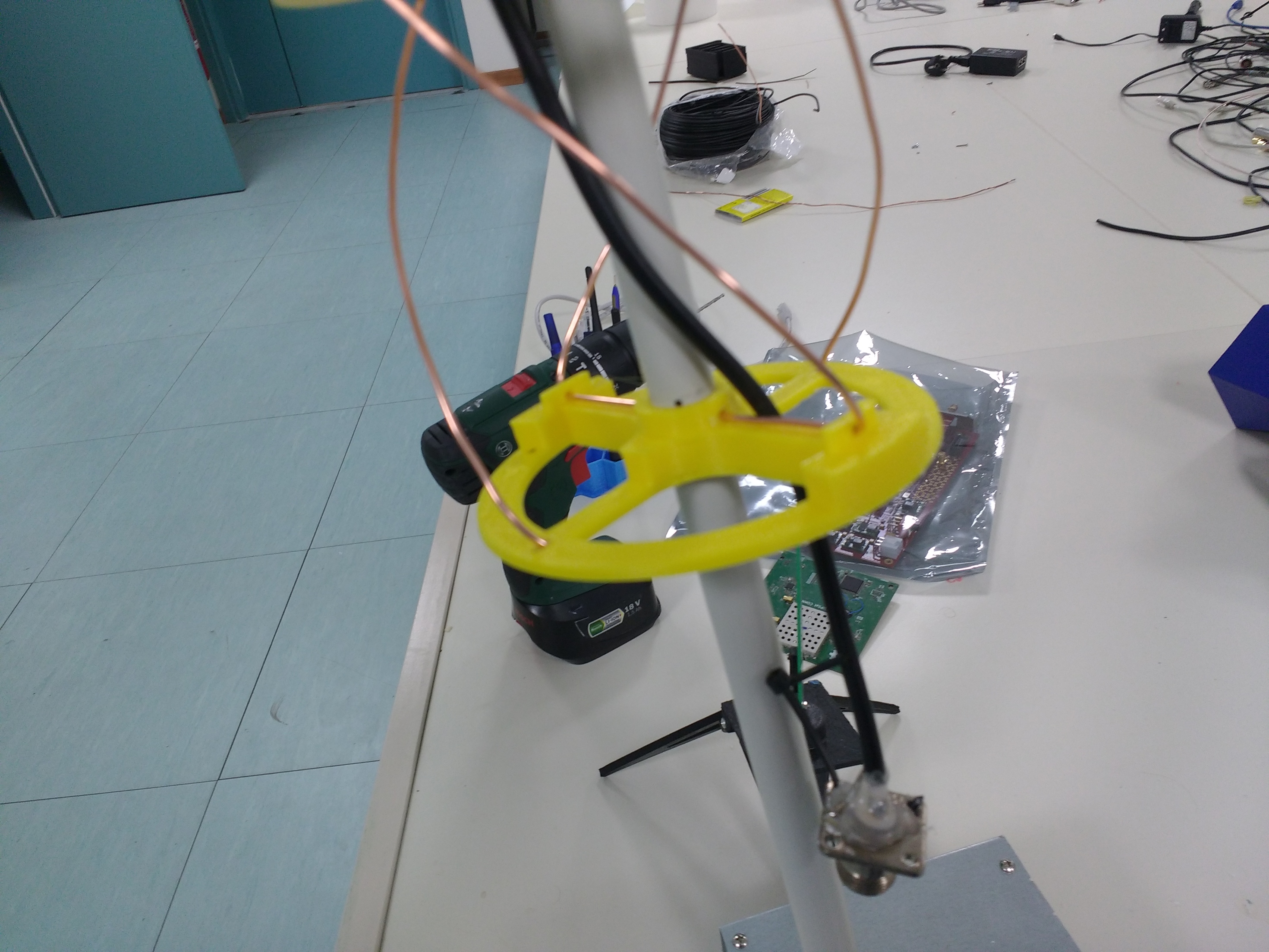
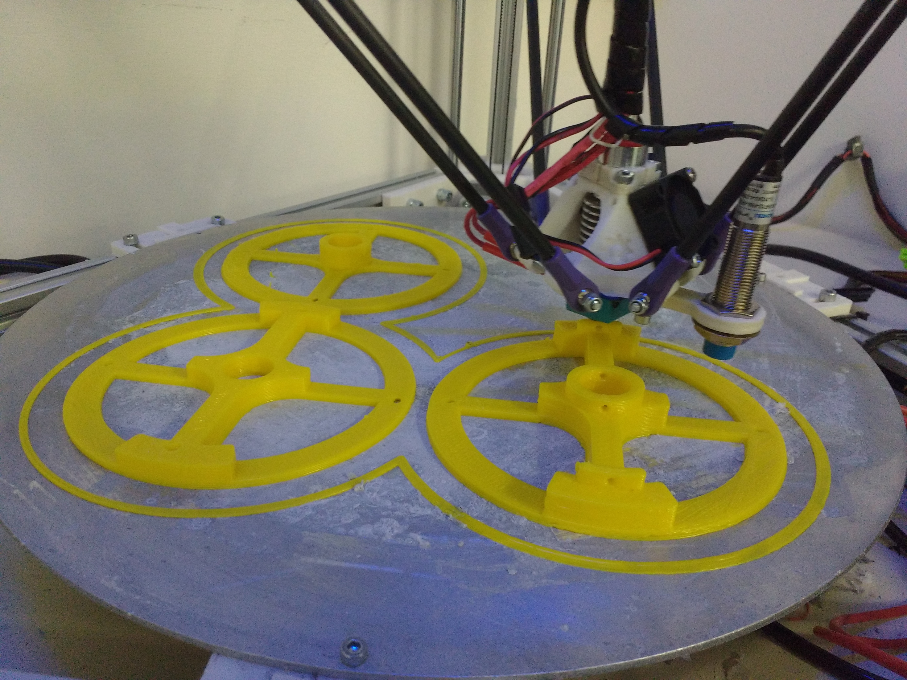
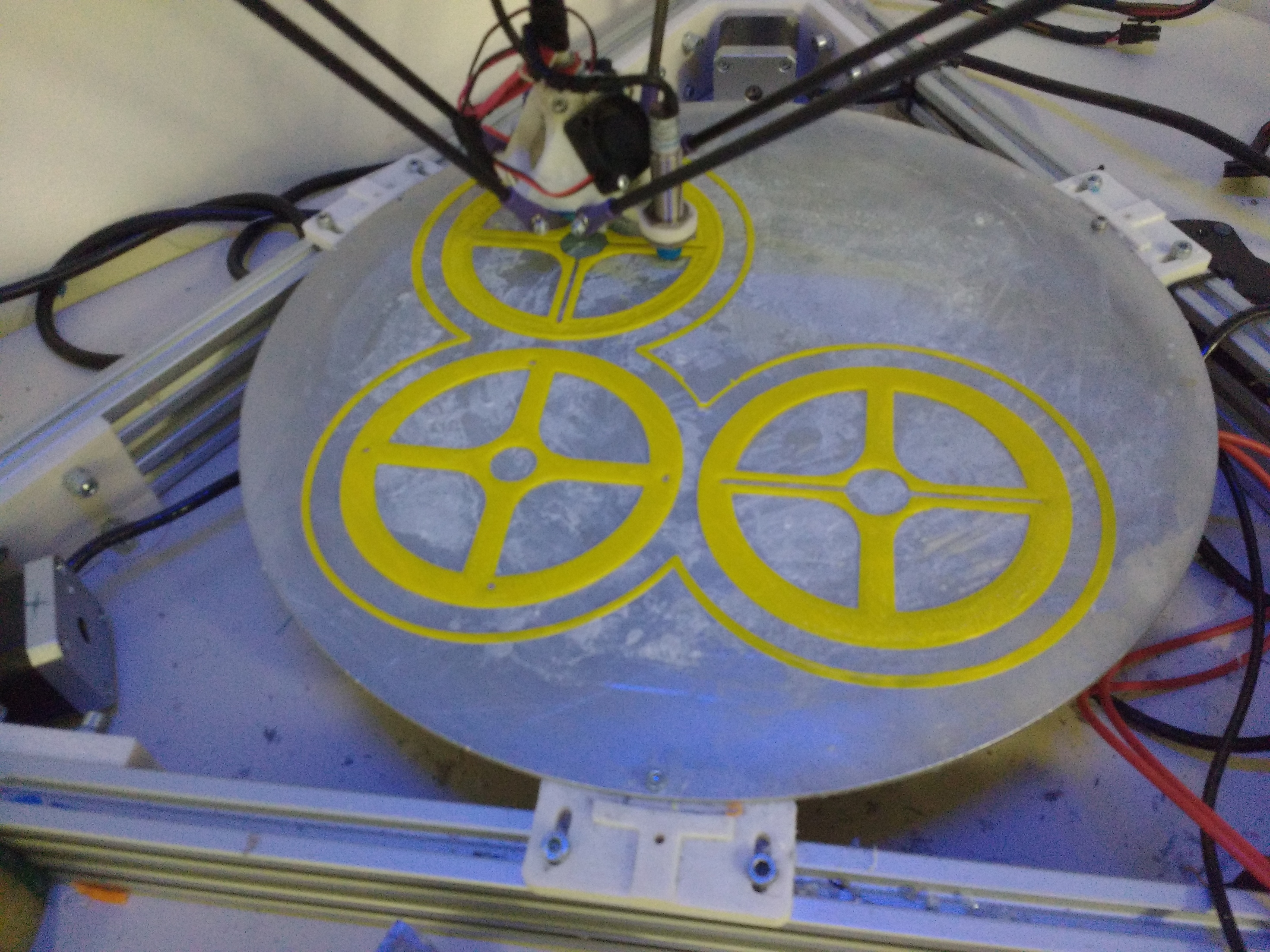
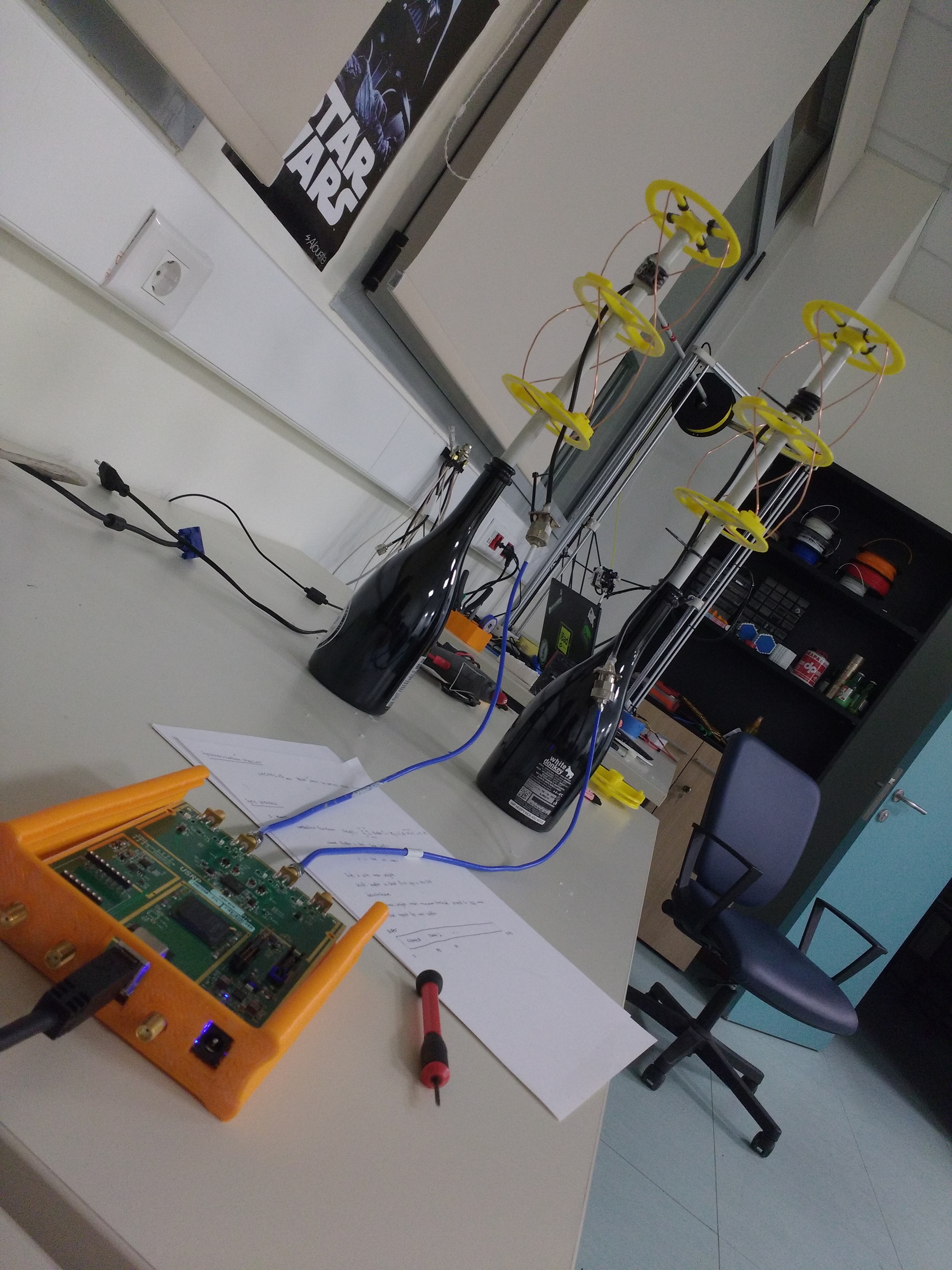
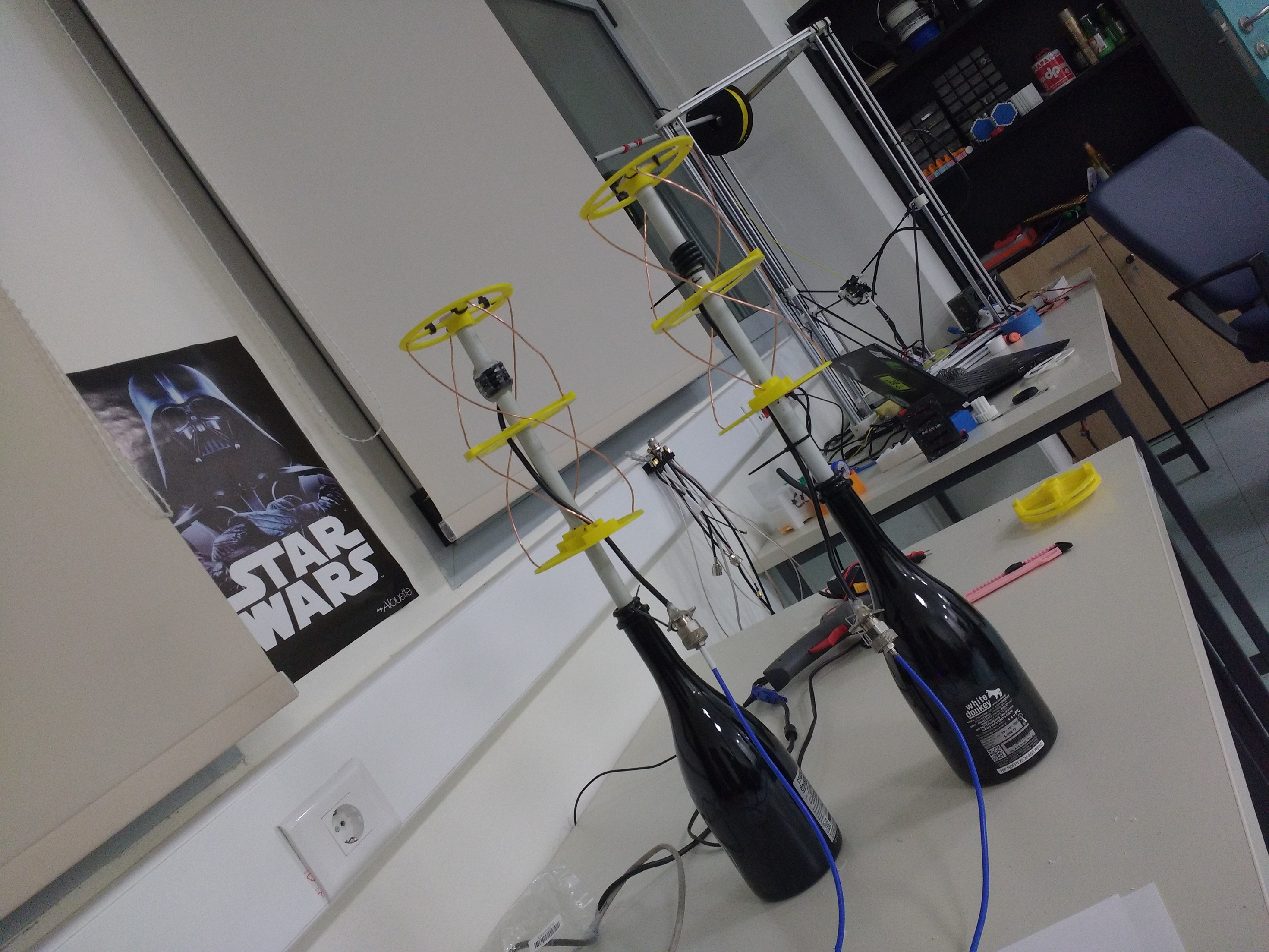
So I decided to make a 3D model using Freecad that would need, “just to put the fucking wire”. The result is relatively good, especially in terms of repeatability. Below are some photos:
It is far from ready, but you can download the stl files for the 433 MHz version. For the mast, I am using a Φ16 electrologist tube, a quite common diameter.
I have been using 137.5 MHz tuned QFH antenna for a while for my station https://network.satnogs.org/stations/22/ performance has been fine, considering my location has obstructions on both north and south side.
Thanks for your design @surligas! Building a QFH was not that much hard as I expect. You made it easy I started to use it around 07:00(UTC) today for my station #1616. Some pictures can be seen from here. Still looking for correct gain, but I have two other questions.
1- I am using a 3D printed part completely outdoors first time and have some concerns about coming hot days. I also covered it with a large plastic bottle to avoid rain. However, does the sunlight or extremely hot weather inside the bottle harm 3D printed parts? How is your antenna nowadays? Can I protect them from hot without disturbing the received signal on the antenna?
2- As I said, I am still tuning the gain, but I wonder the reason of variable snr of observation #4130474. Is it caused due to bad production of antenna such as wavy wire or just the satellite turning around itself?
For outdoors applications I use ASA based filaments. They are UV stabilized and extremely heat resistant. I have some parts for over two years now on the mast of my J24 boat without any issues. The surface finish needs a lot of tuning in your printer especially if you are using a bowden setup, but cosmetics should not be an issue for your case For your antenna make sure that you waterproof the coax. The rest of the antenna should be ok without any additional effort.
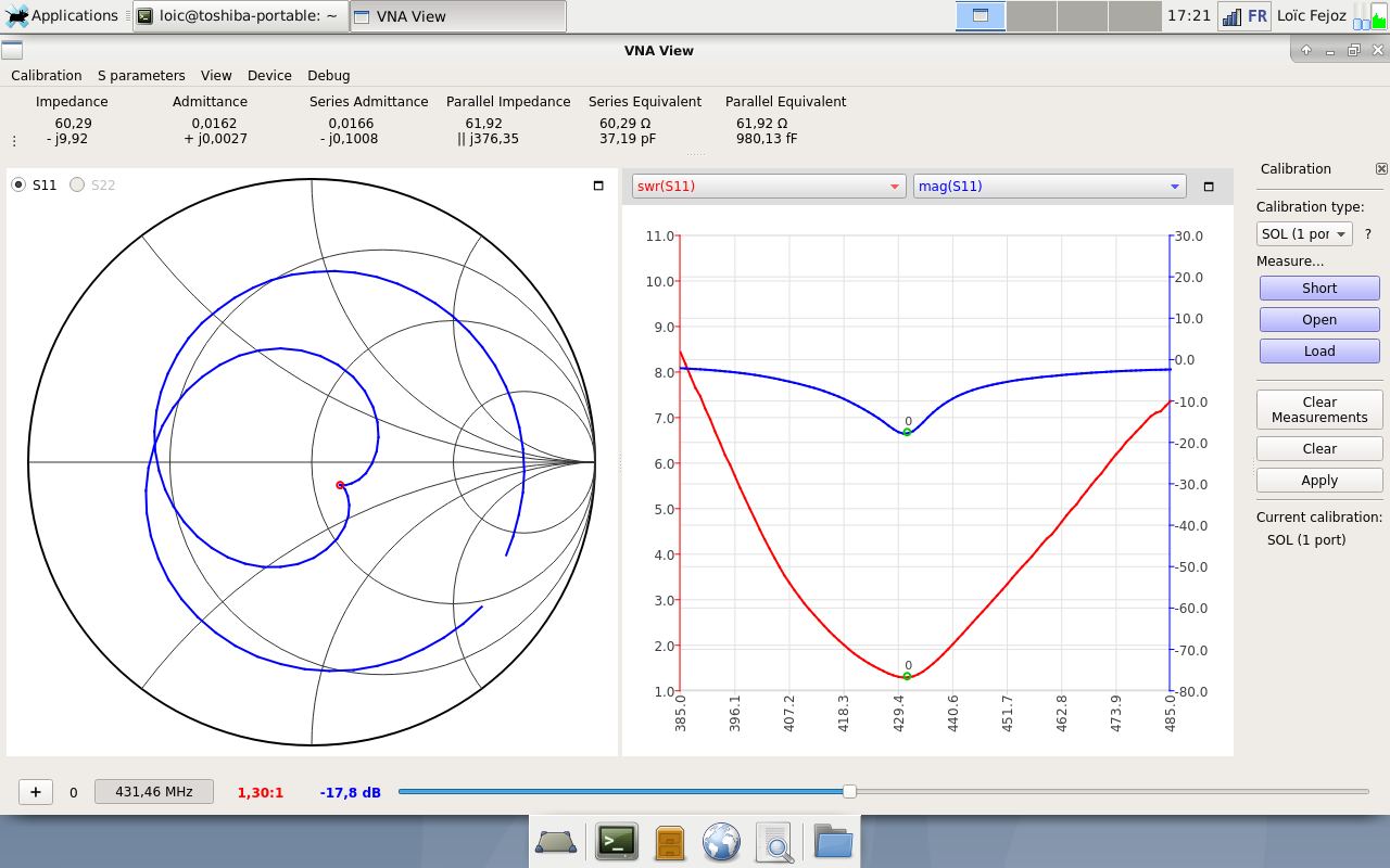
In my case, straightening and tightening the wires was crucial to match the expected SWR on the target frequency.
Actually, I just printed the parts from anywhere in a hurry, even did not think about the material. After I set up the antenna, realised the UV protection might be better. Let’s see how many days can it stand If I remember, I will update here when it is broken. That may give an idea to the people who just thinking to use or used ABS like me.
Do you mean the soldered part on the top of antenna or all of the coax? I do not think water can reach soldered part or connector part of the coax, but excepts of these parts the cable did not covered with something for waterproofing during its middle section (~1 meter) as can be imagine from pictures.
At the soldered part when the core splits with the core, water often passes through it and can travel up to the first connector, causing issues that are very difficult to find. I used Sikaflex which is very durable in UV environments and provides quite descent waterproofing.
I made one of this design but after all the tightening and squeezing best I got is a 1.2 Swr on 422 mhz and 1.8-1.9 around the targeted 433 mhz range. Do you think re-doing the calculations for something around ~445 mhz might do the trick? Any ideas?
I have also just finish this one but haven’t battle tested it yet.
Initially it was at 420Mhz but after shortening it a bit as in the doc.
Now it looks like better:
I also made one and mine is also centered around 420MHz (SWR of about 1.7).
I’ll try to make a second shorter one soon.
As it looks like a common trend we should probably update the documentation in gitlab ^^
I’ve had a go making a few of these for the 70cm band, and I have a few observations:
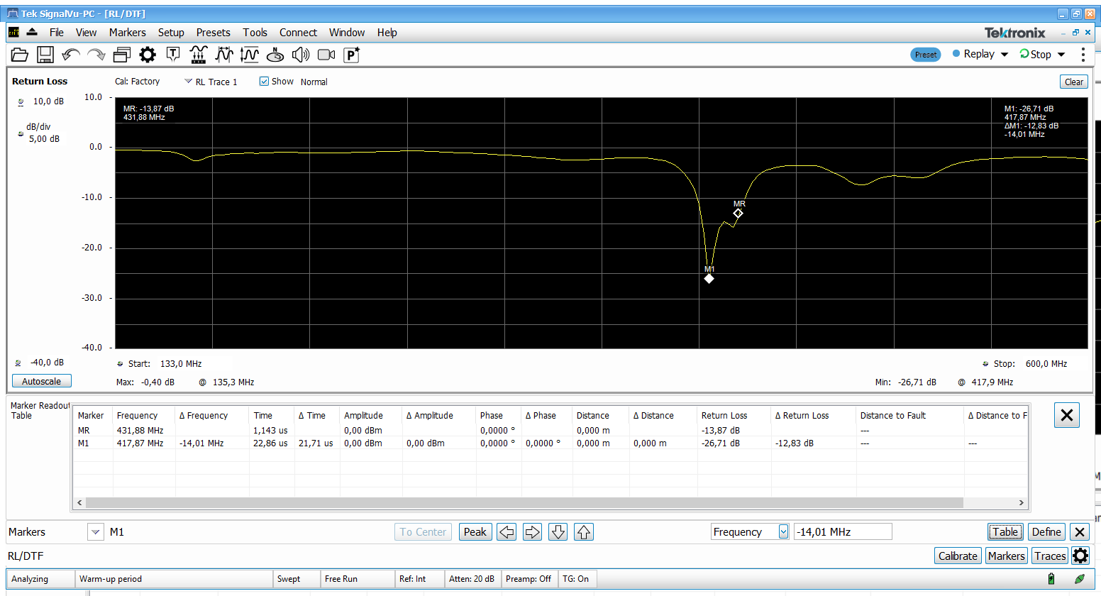
The resonant frequency I end up with seems to be a bit less than the design frequency (by maybe 10 MHz).
I can get two out of three of the following, but never all three at the same time:
Resonant frequency (based on return loss) where I actually want it.
Hemispherical Pattern
Proper Circular Polarization
I am testing the pattern and polarization using a sig-gen and a dipole antenna about 15m away on my local antenna test range (local park). I test the polarization by pointing the antenna at the dipole and rotating the antenna around its long axis while monitoring power levels with a spectrum analyzer. If it’s properly circular then the power should not change as the antenna is rotated, as linear → circular always results in a 3db polarization loss. When things are not right, I’ve found that i’m getting 10-20 dB polarization mismatch nulls.
The pattern is tested by ‘swinging’ the antenna back and forth to get an elevation cut with respect to the dipole. Again, I often see 10-20 dB nulls instead of the nice smooth hemispherical pattern.
So yeah… I just can’t seem to get the proper performance out of it. I suspect the coax running down the center of the antenna may contribute to this. Also, the matching arrangement using a long and short loop is way too finnicky to get perfect…
I’m considering trying an alternative feedpoint arrangement using a 90 degree hybrid combiner (or a 0 degree combiner and a 90 degree phasing coax), and two matching transformers (to match the loop 100 ohm impedance to 50 ohms). This way both loops can be the same length.


 I started to use it around 07:00(UTC) today for my