Hey y’all, I need help. I have Yaesu g-5500 rotator and gs-232b there is a problem with elevation control. I use HRD Sat Tracker app for satellite tracking so when i try to track a satellite azimuth is always fine but elevation is not properly tracking. For example in order to hrd app says rotator should be in 23 degree but by rotator stuck at 16-ish degree. When antenna rise and decent both ways there is a stuck area +16 degree. In these degrees, i need to press a “elevation down” button while elevation needs to go up to give a impulse like “hey rotator come on” then rotator works properly when i do that. The problem is it needs to be automatic. so if there any solution for it please hmu.
Hi,
May be you can check to look if the wire is well set on rotator controller like this:
| Number | Colors |
|---|---|
| 1 | Brown |
| 2 | Green |
| 3 | Blue |
| 4 | Red |
| 5 | Yellow |
| 6 | Black |
Seems has you had a “motor stall”… it happened to me some times ago.
Check this:
- Load balance on the elevation arm: the antennas had to be well balanced regarding the elevation axis. In case add some “weight” to the back side of the mast
- proper wire cabling from control unit and rotator; pay attention to the electrical wire section too
- check the comms from rotor to controlling software, sniffing the commands flow, either via software or hardware, looking if thre’s some strange.
My two cents
I3VFJ, Vittorio
Hey thanks for reply. Its seems your 1 and 2 steps are ok with my system. What kind of methodology i need to follow for your suggestion 3.
Another possibility it’s a potentiometer failure into the rotator unit… try to drive it around the “16ish” degrees position and with a multimeter connected to the pot contact look carefully if the voltage changes it’s smooth or no.
Well, I dont know about HRD… if it use rotctl as media to communicate, try -vvvv switch on teh rotctl command line.
To sniff in hardware I had found very useful a simple circuit with USB/RS485 adapter.
You need 3 units, all wired on the A-B circuit: one usb port connected to HRD (in your case), 2nd port to the rotator controller, and the 3rd to a terminal program ( Putty, Cutecom, or similar).
So doing all the traffic between tracking software and antenna rotator it’s available on the third port without interfering at all.
It’s also possible to send GS232 msgs to rotator to move the antenna and/or read data from it.
I use this in underway developing / debugging my rotator control driven by Gpredict ( some refinements to do but not had so much time …).
Hope that this help… 
de I3VFJ, Vittorio
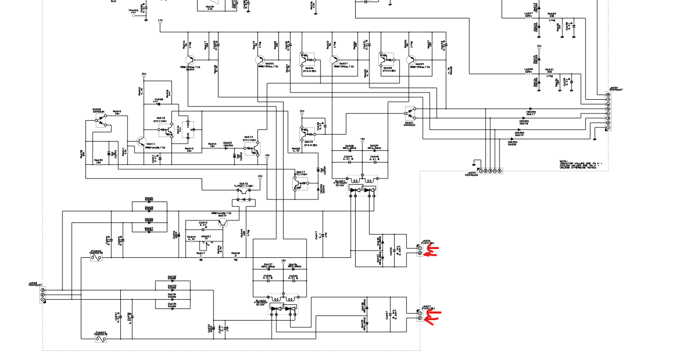
Hey, thank you a lot Vittorio. I just found a schematic for yaesu 5500dc. There is bunch of potentiometer the potentiometer that you mention into Elevation Rotator itself right? I mean, i need to tear a part elevation rotator. right?
Yes, the main candidate is the potentiometer inside the elevation rotor. But disassembling it isn’t so easy… Try to manually slowly change the elevation around 16° via the control box and measure the voltage that comes from it ( look at the schematic to figure out which pin of the control cable carries the position voltage).
Let us know any news 
Hey i finally take down to rotator from tower and make some measurements. From elevation rotator 1,3,4,5 pins are short circuited with azimuth rotator. Pin 1 is shorted in the schematic its okay. Pin 3 is grounded so its okay. Pin 4 its going to relay and also Pin 5 going to other relay but I cant follow the circuit. But they are short circuited someway with each other. I can’t say anything about it because I cant follow the circuit. If you have any comment on that issue it would be great. My next move gonna be the voltage measurement from pot. Thanks
HI Heaviside,
sorry for delay, I was in vacation!
So, it is not clear which pins you are referring to.
On the rear of the control unit there are 3 connectors: one 8 pin DIN and two 6 screw contacts ( azimuth and elevation).
You have to check, better with an analog voltmeter or an DC coupled oscilloscope, the voltage between pin 2 and 3 on the elevation connector: manually commanding the elevation you can see that voltage change.!
Then have a sharp look when the position is around the critical point: the change “has” to be smooth, without “jumps” .
If you see some “jumps”… there’s a failure in the pot inside the rotor 
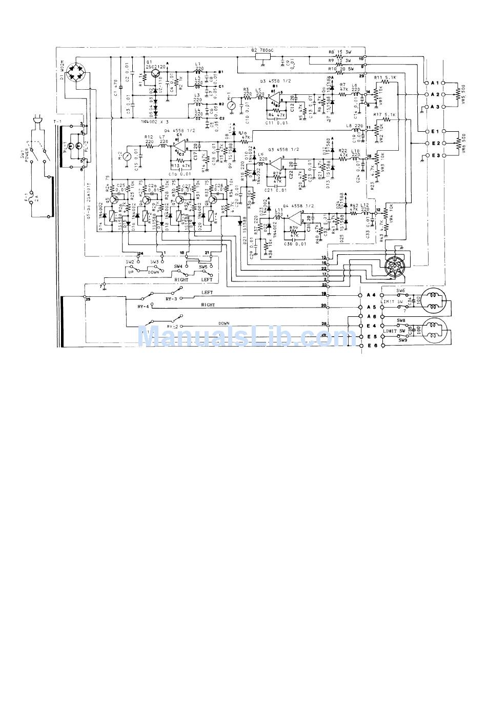
For these istruction I’ve looked at this schematics:
Hope that this can help to solve your issue
Let us know…
73’s de I3vfj, Vittorio
Hey Vittorio, I am using DC version of Yaesu G5500 so that pins i am reffering is azimuth and elevtion pins itself. What I am try to say is elevation pin 4 and azmimuth pin4 are shorted also elevation pin 5 and azimuth pin 5 shorted. I just attached schematic. You can track from elevation terminal block to azimuth terminal block. Basically E4-A4 and E5-A5 are shorted. They are going to relay but i couldn’t track the circuit. Pot seems fine its changes smoothly no jumps.
Thank you.