Problem is, I don’t even know if they fit, they fit over the pvc pipe ok, but not sure how it’s all going to work out until I get the frame and parts installed.
I used freecad to modify the cad files Satnogs has, I started by making the diameter of the hole the same size as what some of the websites state 1" US PVC Outer Diameter is, first few prints did not fit, I had to keep making the hole a little bit bigger (but not too big). Nice thing is, looks like there’s some nut/bolt spots on the collars and what not to tighten things up.
The parts I modified and created:
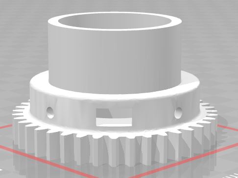
Modified - Axis Gear 5601 (Made it longer so it fits into the 40mm bearing and the inner diameter will fit over 1" pvc)
Modified - Axis Gear Flange (Just changed the inner diameter to fit over outer diameter of 1" pvc)
Modified - Axis Gear (Changed the inner diameter to fit over outer diameter of 1" pvc)
Modified - Axis Spacer (Changed the inner diameter to fit over the outer diameter of 1" pvc)
Modified - Homing Ring (Changed it to where it will work with 1 1" pvc, this actually sits inside of the Axis Gear 5601 piece above, and what will trigger the stop switch)
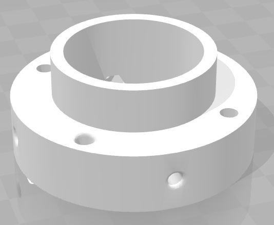
New Part - 40mm bearing adapter which will basically fit into the Axis Gear part and slide into the 40mm bearing. (I ordered 40mm bearings when I ordered all the rest of my parts so had to come up with something to make it fit)
Example of the 5601 Changes:
Original
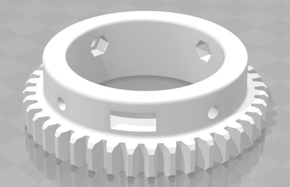
Modified
Picture of the 40mm Bearing adapter I made. Not only will it tighten up around the 1" pvc with nut/bolt spots, it will also bolt onto the existing holes on the axis gear
One thing I just noticed on the 5601 Gear I modified, is it doesn’t have the little taper on the ends of the gear part. I hope that doesn’t affect anything… /sigh