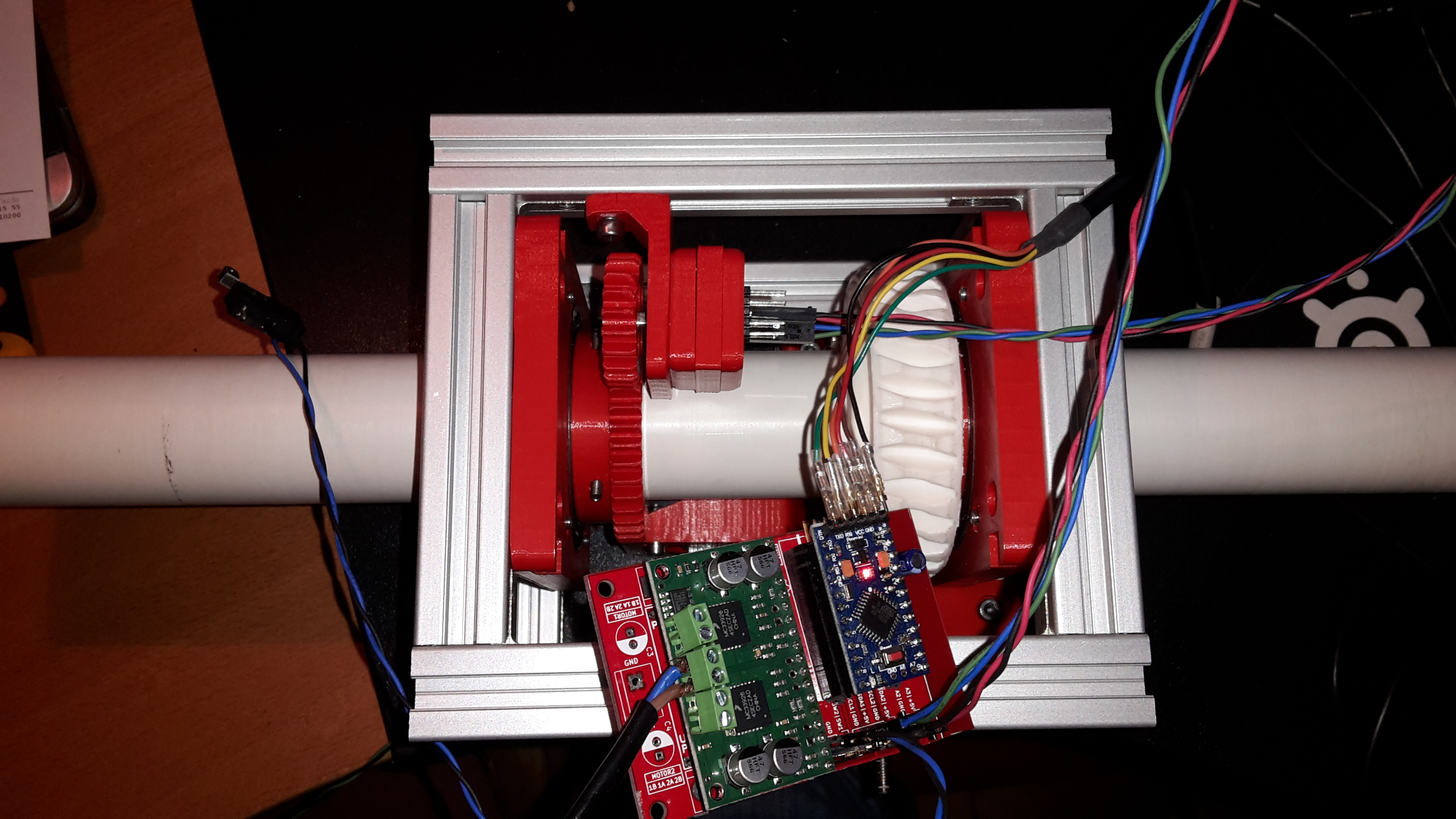
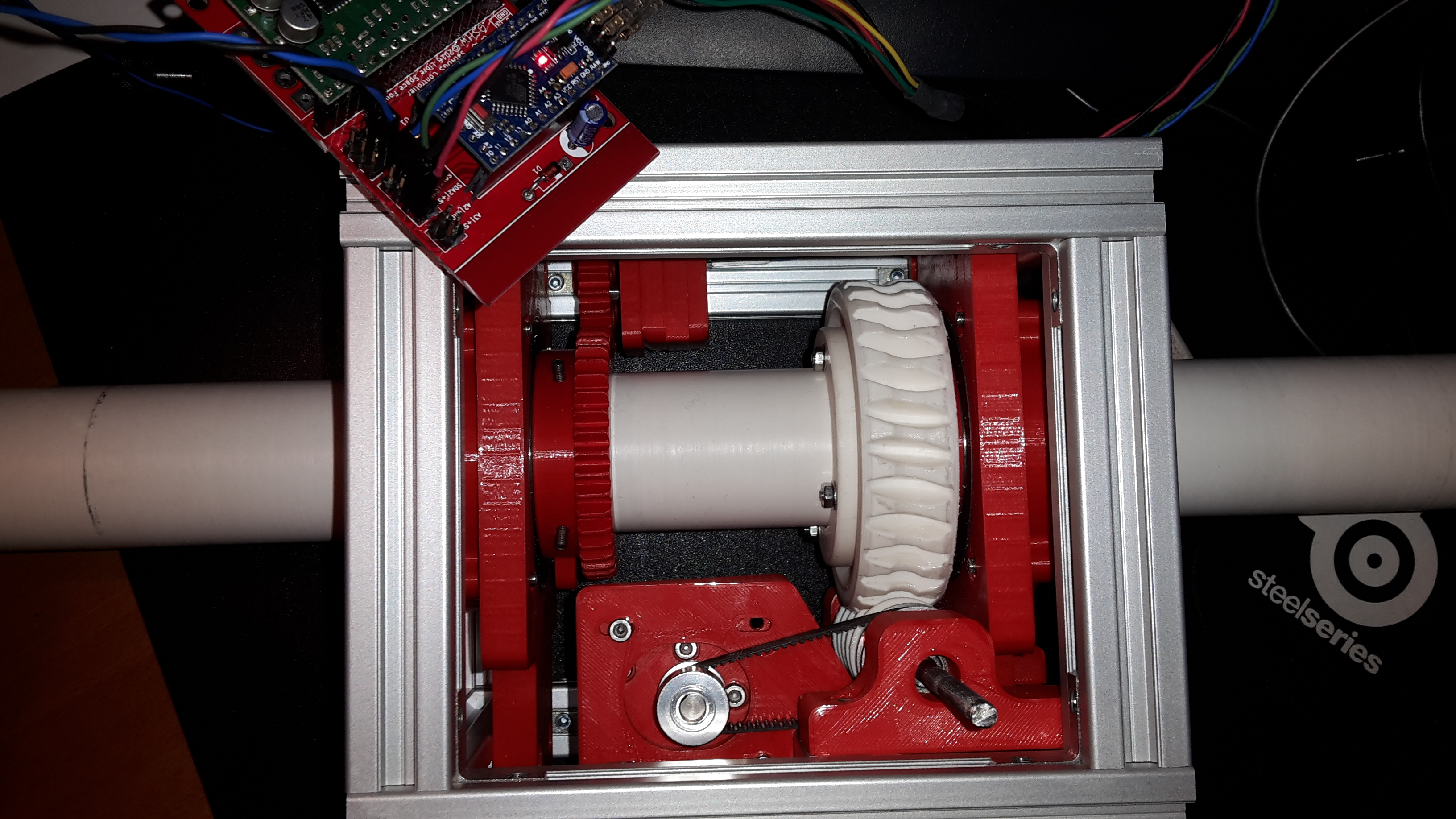
Two pics from my v3.1 version of the DC motor rotator with v2 version PCB
9 Likes
Took some time, but finally moving.
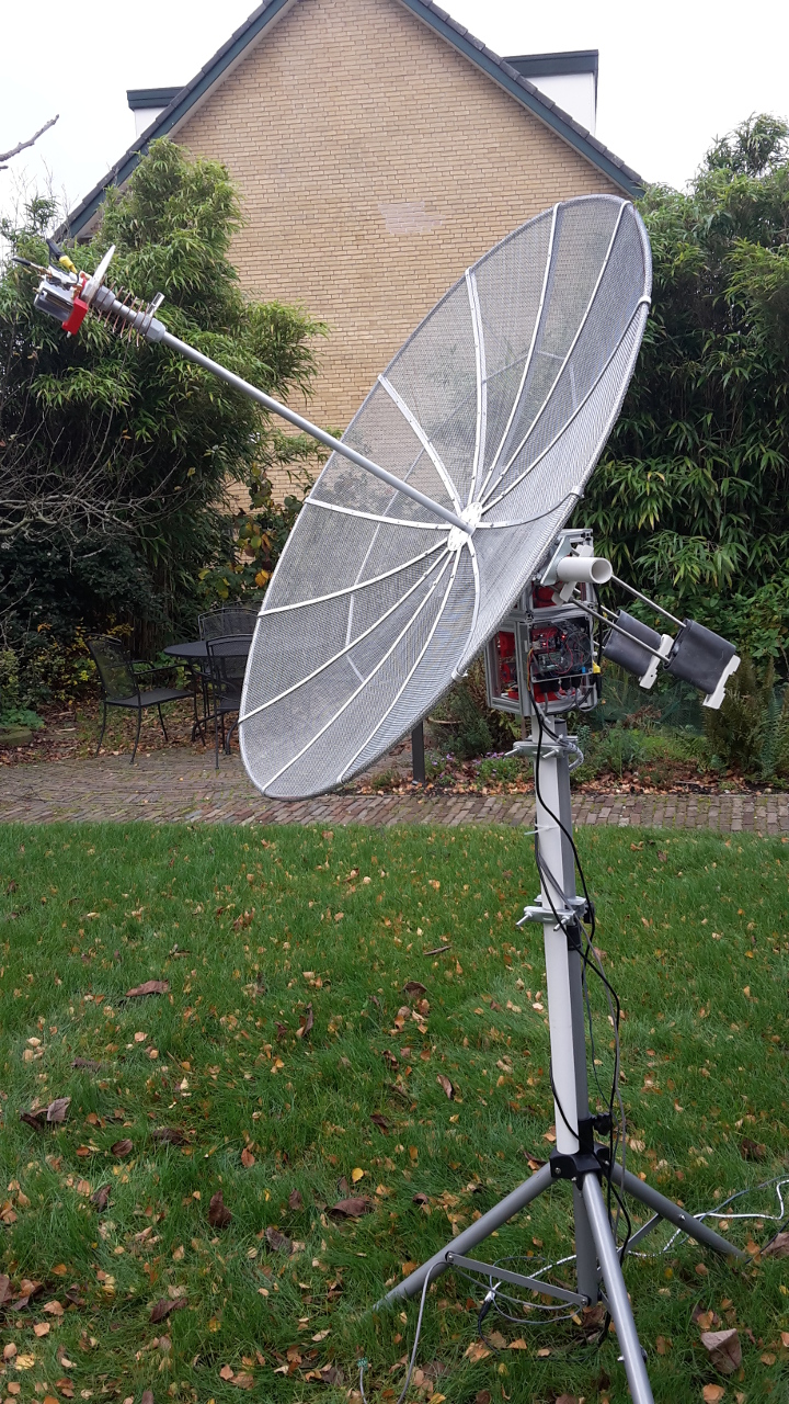
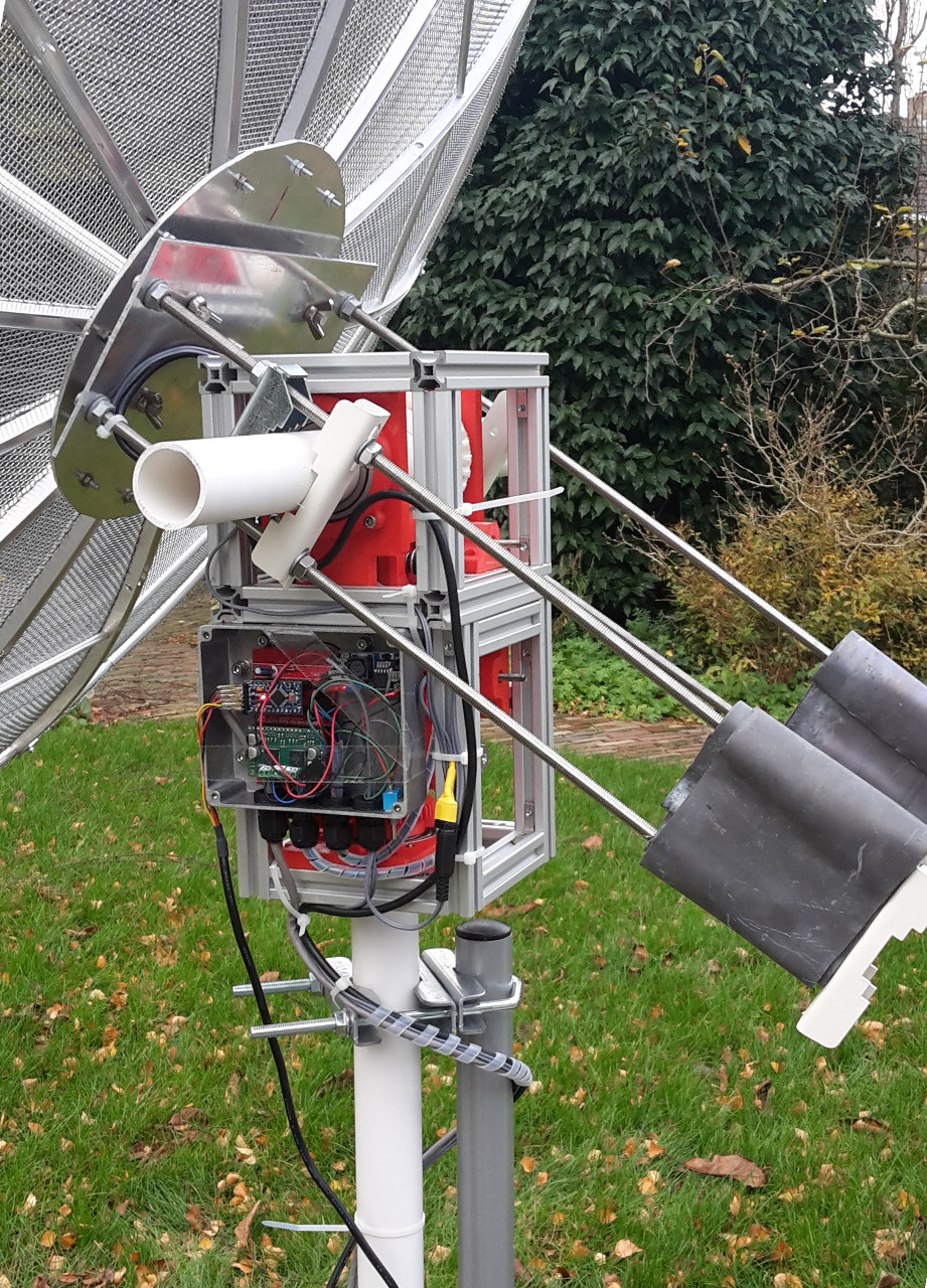
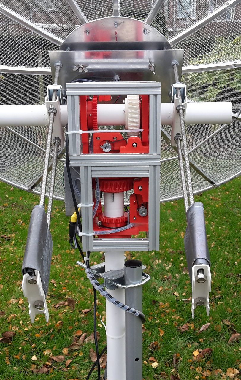
The dish is really at the limit of what it can bear. Quite some oscillation I had to solve.
I rewrote all the control software with the Arduino PID library. Will upload when I cleanup a bit.
9 Likes
Nice! Are you going to try NOAA HRPT on 1.7 GHz with this setup?
Yes, that is the intention. I already tracked NOAA-19 and METOP-A but just made SDR recordings. Did not try processing yet. Also tested on METEOSAT-10 LRIT and had good signal there too. End goal is full hardware decoding based on the work of Werkgroep Kunstmanen, a Dutch group that built its own hardware. Dish is also self made.
This is phenomenal work @ph4as ! Thanks for the share
Really looking forward for this!
Hi,
Decided to create a new repo for this. On github as I already had an account there:
It was so deviating from the original dc_motor_control that I thought it did not make much sense to push it on top of that one. Let me know if attribution is clear enough etc.
For now it is very much work in progress. First I want to clean up and get RS485 working nicely (transparently).
Then add safety and settings storage such that I can experiment without reprogramming too much as with the RS485 that is a pain of pluging in and out.
2 Likes
Very nice 
What resolution do you get out of this setup in azimuth and elevation?
I suppose the extruded aluminium was bought online?
Care to share? I’m interested in replicating this setup and trying with a 1m10 offset dish.
Resolution in an absolute sense is difficult to answer with lack of accurate measuring possibilities.
The encoder gives 12 bits per half turn so (1:2 gear) so ~ 0.044 degree steps.
For azimuth I get about 0.15 degree from the setpoint, but there is a little play between outgoing axis and encoder gear.
Azimuth only has to fight with the inertia. It already moves with a PWM input of 10 (out of 255).
Elevation is worse as it has the full load, so gravity and inertia and torque depending on amount of balancing.
The whole structure has flexibility here and that is after the encoder. From the encoder I also get at about ~0.15 degree to setpoint but with a long settling time as it is the I term from the PID that has to get it there. Not clear what the accuracy in motion (tracking) is. The rotor only starts moving with about 115 on the PWM. So there is quite a lot of stiction and friction, which makes it jump and overshoot when it tries to correct small setpoint errors.
Overall I would judge it is more like 0.5 to 1 degree accurate. I cannot easily judge if this is the tripod, the ABS 40mm pipe, or the rotor. For the pipe I want to try aluminium but you need accurate pipe to get it through the bearings. The ABS I had to turn down on the lathe.
You can also checkout: https://tysonpower.de/blog/diy-az-el-antenna-rotator-for-under-150
It really depends on the weight of the dish.
I’m also considering a diseqc rotor like:

(dutch magazine: http://www.kunstmanen.net/index.php/2012-10-01-09-31-09/archeif)
Diseqc I believe does something like 0.1 degree steps.
I’ll create some build blog somewhere the next 2 weeks or so and update here.
1 Like
Indeed, a DiSEqC solution is quite neat but they can be quite noisy from an electronic point of view.
But you could shutdown the 12/18V when the dish has reached position.
All satellite style DiSEqC rotors require some serious mechanical modification since they are intended for just following the satellite belt.
True azimuth DiSEqC rotors do exist (google Eagle Aspen rotor) but are very rare and not available in Europe. There is however some interesting source code at:
https://code.google.com/archive/p/mc-satellite-antenna-rotator-project/
https://drive.google.com/file/d/0B7hVB7ocX4MBejlNbS02WFNJelU/edit?usp=sharing’
which could be of interest. Uses a Raspberry Pi to generate DiSEqC messages from Python.
Thanks. The DC rotator makes quite a bit of noise too though, more than my regular diseqc rotors. Mostly the azimuth because it is not easy to increase the PWM frequency. The satnogs PCB uses the PWM pins of Timer0 for azimuth and when you want to increase the frequency the clock runs too fast. And the clock is used in the PID library, so you end up having to change code everywhere to compensate. Or change the default library.
The noise mostly happens when the PWM is too low for the rotor to move. It could also be removed by creating a deadband. When I tried the stepper motor it also was quite noisy, but I think that is because by default satnogs uses full stepping and not micro-stepping. Never tried that in the end to hear the difference.
The elevation rotor is running on high frequency and is quiet.
The alu extrusions are from the suggested supplier Motedis (http://www.motedis.com/shop/). I had them cut to size which was quite convenient.
Hey!! Nice job with the rotator  , it would be nice to make a pull request to satnogs repository.
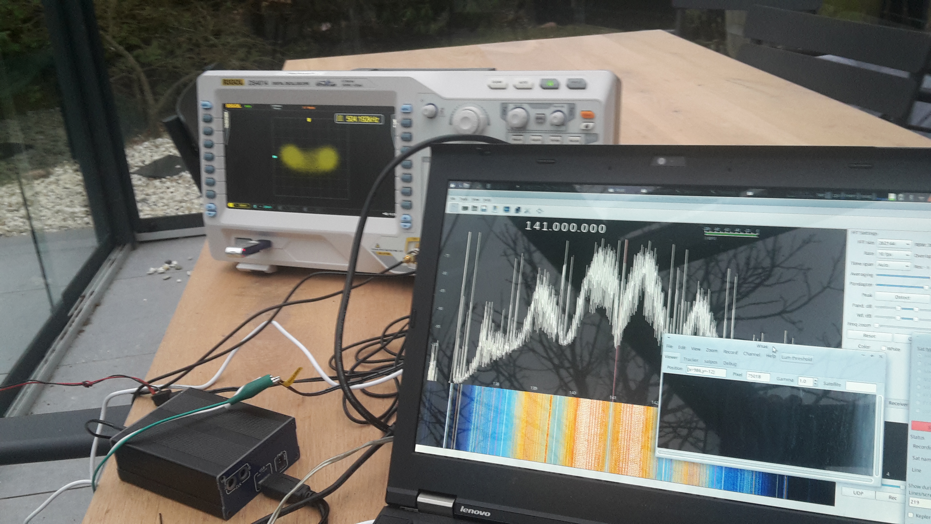
Finally first image from NOAA-19 this afternoon. Only less than half as I was tuning the hardware to start locking.

Setup was with dedicated hardware from http://www.kunstmanen.net and Rob Alblas: Hardware
I had LimeSDR running in parallel with GQRX to make sure signal was ok. Downconverter is an old LNC1700 downconverter (1557 MHz down). Then wsat to do the decoding with an FPGA board. (Software.)

7 Likes
Sorry to bump such an old post, but how much did this dish weigh? I’m trying to determine what the max load is for the rotator.