The existing commercial rotators usually have either AC motors or DC motors, according to
this review and this list. Also in SatNOGS Network, until today, they are 39 ground stations with rotator. Almost the 90% are Yaesu G5500. An average number of observations per day for one station are:
in 1h, at least 2 observations of 15min each
in 15000 hours, 30000 observations
which means almost 2 years
So all the system (mechanical and controller) must achieve a large MTBF.
The mechanical failures, if the antennas are balanced and the rotator isn’t working in extreme environmental conditions, are limited. The most usual failures are done in controller due to electromechanical switches (relays).
In order to replace the commercial controller must be developed either 2 different controllers for AC and DC motors or an universal controller for both types of motors.
The existing documented solutions for DC motors are:
SatNOGS controller with modified motor driver in order to drive bigger DC motors.
SARCROT, that you can select the driver according to DC motor power.
The existing documented solutions for AC motors are:
SARCROT, The Mk1c version, which uses triacs to do conduction angle control (thanks @vk2byf).
As described in this application note the use of triacs and conduction angle control
is low efficient and introduce harmonics (which in our application are in low frequencies).
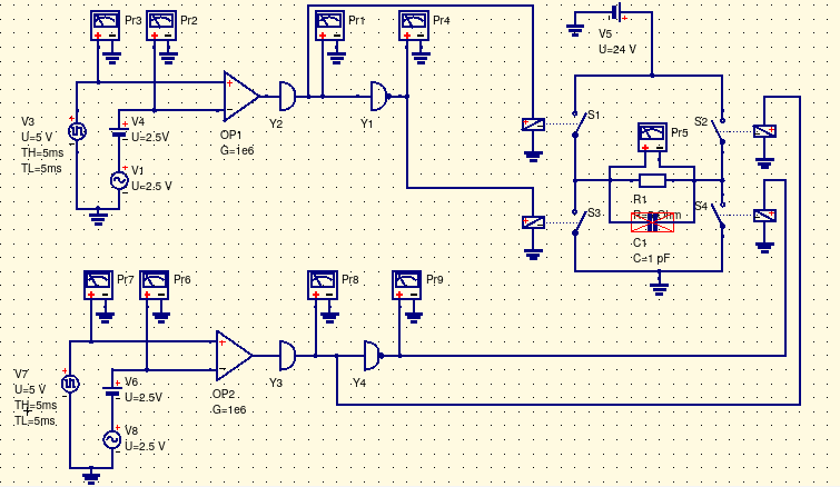
Another method to control an AC motor is to use an inverter. The input voltage of the system would be low voltage DC. The system would be consist of a H-bridge that driven by SPWM
in order to produce a variable frequency sine, by using a filter in the output of the H-bridge. The same circuit could be used to drive DC motors by using PWM to drive the H-bridge.
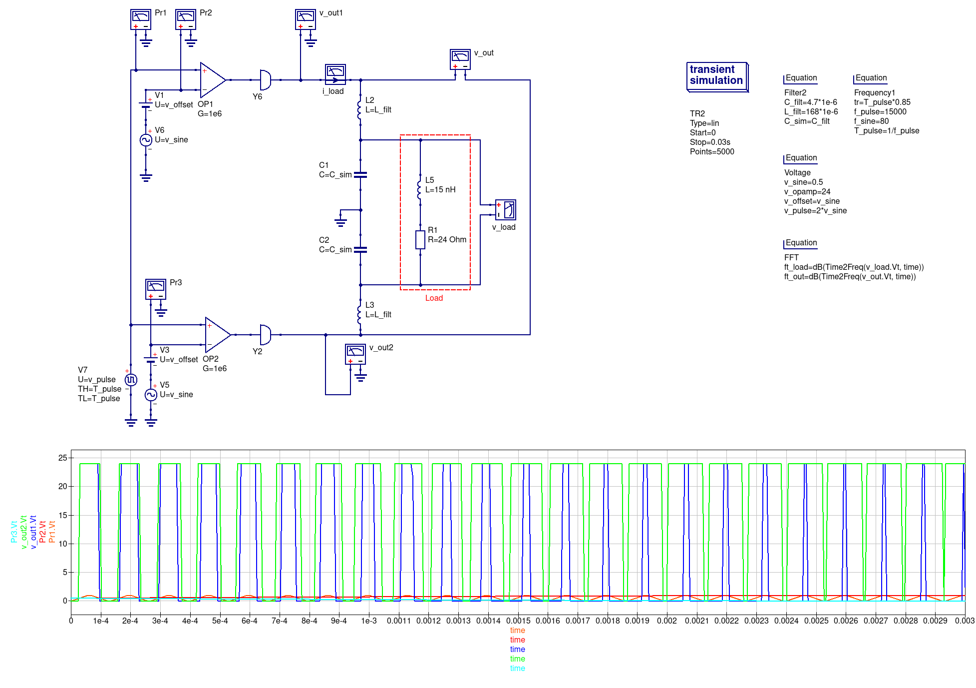
A simplified QUCS simulation is presented,
I think that this approach is awesome since it provides us with the opportunity to create a truly universal solution for the vast majority of the rotators out there (including of course the SatNOGS rotator) and would unify the open source (or open source to be) efforts and community around them.
@azisi keep us updated on the tests and practical feasibility!
If you don’t mind I would like to invite Phil Karn, KA9Q, into this thread as I have had a very good conversation in Friedrichshafen about exactly this with him.
Very nice works @azisi
Also, the survey you made is very useful
The idea we have been working with at OZ7SAT is that for AC motors we generate a sine wave using the DAC of a processor and amplify it using an audio amplifier IC. OZ2ABA found some good amplifiers that can be used.
I like the SPWM approach much better because of it is high efficiency. The amplifiers will be losing too much power while the SCRs will be producing a hell of harmonics which will be heating up the motor.
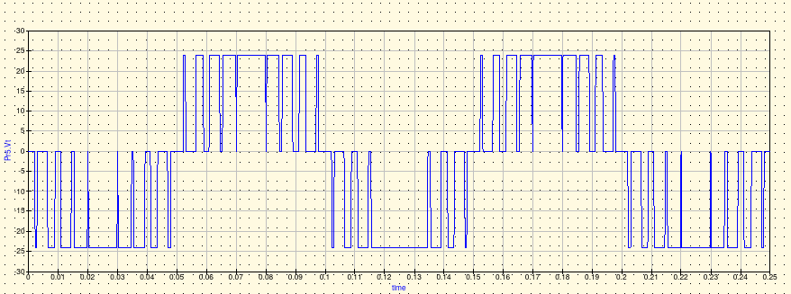
Firstly, in order to produce SPWM the code of this repository was used without filtered the output to smooth the pulses and generate the sine wave. In this situation the frequency is measured and is almost the same with the frequency that the board is programed. Also the output voltage
was Vpp =~ 24V (peak - peak), because the Vmotor of board was 12V. Then the induction motor was connected to the H-bridge with the phase capacitor, that is used to produce 90deg different phase between the two phases. The induction motor was tried to move but wasn’t rotated.
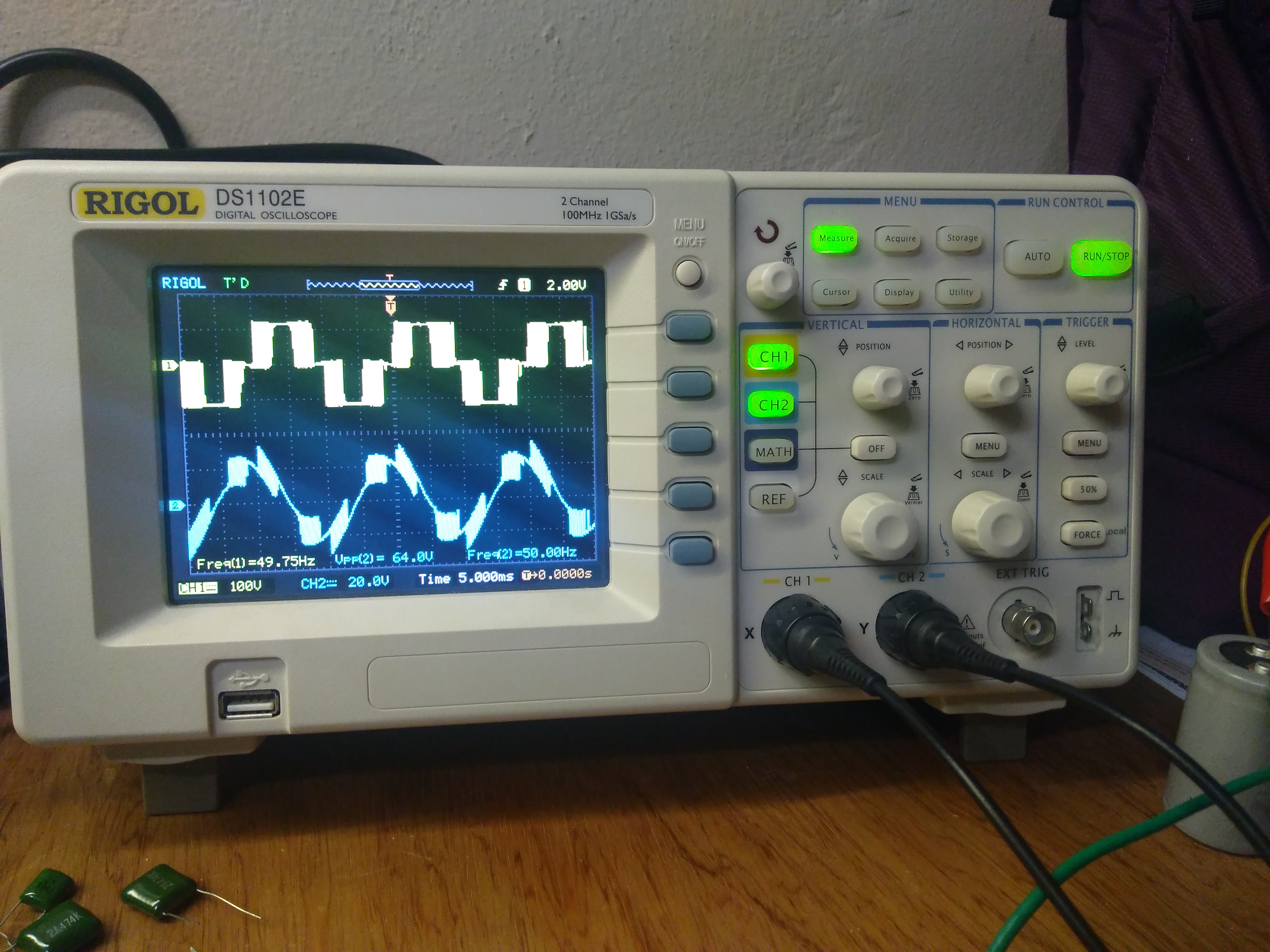
The yellow signal is before the capacitor and the cyan signal is after (the measurements of Vp-p weren’t correct
in this picture). After a modification in PCB (the Vmotor is the same with Vin of board), the Vmotor was changed to Vmotor = 32V so Vp-p =~64V. The motor started to rotate with 50Hz frequency. Finally the frequency changed from 10-80Hz with the motor changing speed.
Finally, by using the same driver and by adding filters in the output, AC motors could be driven.
Next steps:
To discuss about the specification of the board (hardware and firmware).
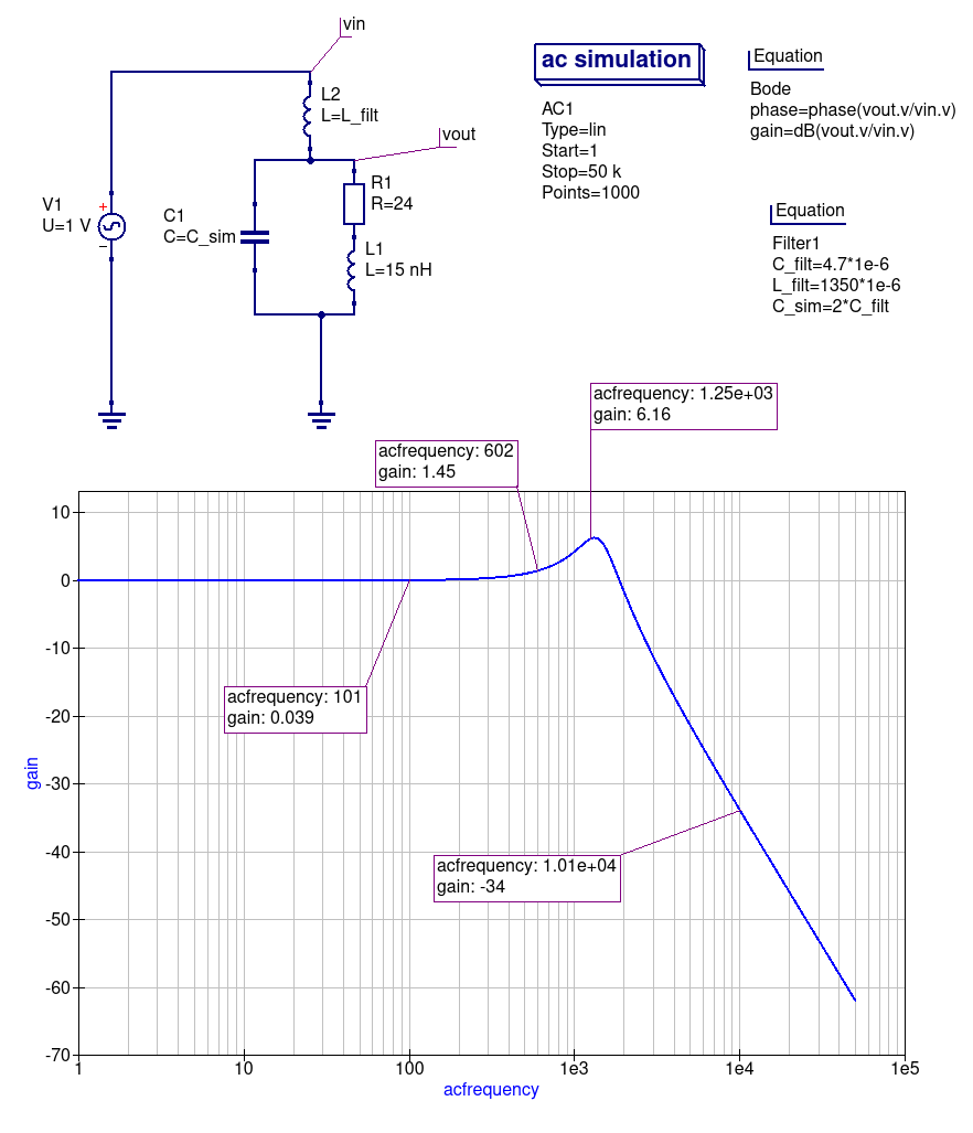
SPWM Filter:
To cut-off the unwanted frequencies of SPWM method, a L-C filter is used.
An application note and calculator is proposed from ti.
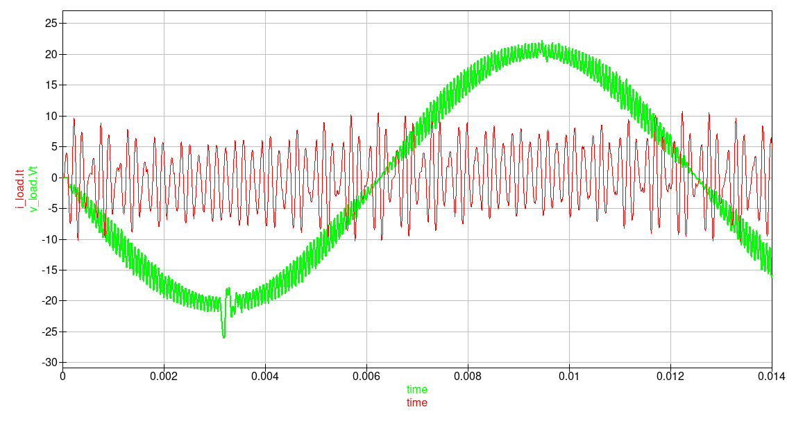
A QUCS simulation is made to evaluate the response of filter and the voltage-current output with load of SPWM method.
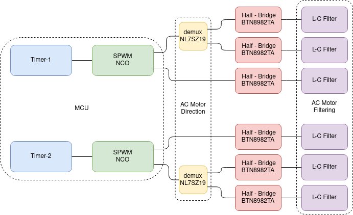
AC motor control Implementation:
Τhe difficulty in implementation is how to change the direction of AC asynchronous motor with squirrel cage rotor. For that reason 3 half-bridges in combination with a demultiplexer are used.
The demux is used to change the SPWM to different half-bridge.
The velocity is proportionally to frequency of sine that is controlled by NCO which will be implemented by a MCU.
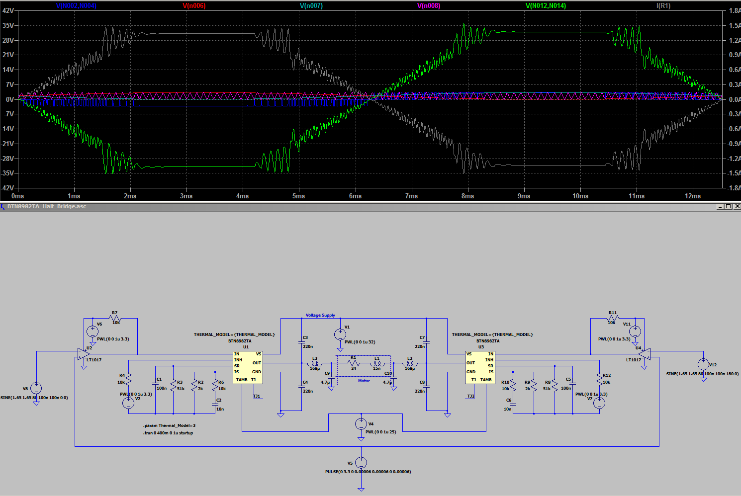
The schematic and (in near future) the PCB is here.
To evaluate the response of proposed topology with half-bridges a LTspice simulation was done. A note: I use LTspice because i can’t find any way to import spice model of BTN8982TA in to QUCS. Any suggestion!!
Hey! Two I2Cs because the IC AS5601 doesn’t support to change the address. The temperature sensor will be placed in the board, just for monitoring the temperature inside the enclosure. The half-bridge it has protection for over-temperature.


 )
)
