I would recommend using the main branch of the k3ng rotator and not a 7 year old one.
They also have a excellent wiki, documentating everything.
I’m running a similar setup, but built the hat myself and just used the default pins configuration.
You can see in the commit what was changed.
Thanks for the response!
I took the code in the main branch and configured it similar to the commit. However, when I try upload it, I am getting the following error:
What redundant sections of this branch should I cut out so that it won’t exceed the Arduino Uno’s memory?
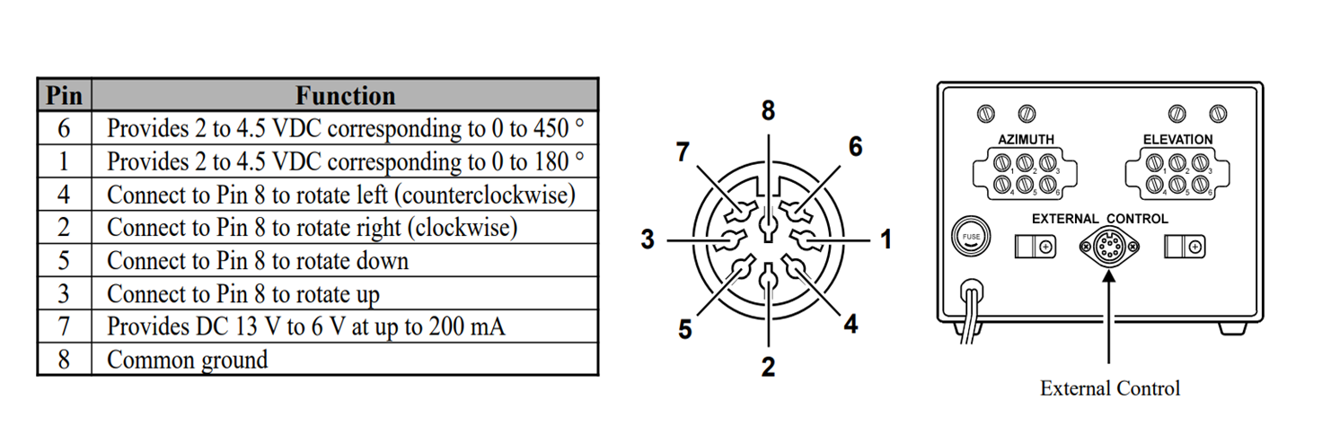
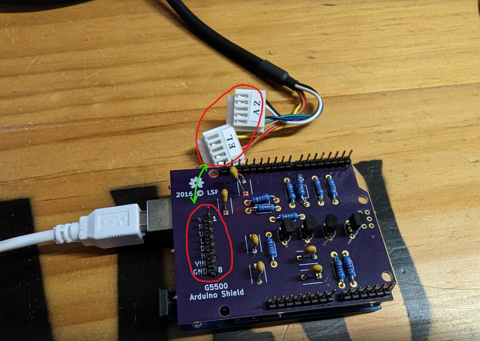
Furthermore, we weren’t sure how the pins in the code (1-9) corresponded to those on the shield, and how the physical connections with the port should subsequently be made
Aha. that means the project has grewn to the point where the default conf + our needed features not longer fits the uno. I’d recommend disabling features that is not needed, like the display and gps, perhaps more ?
Regarding the pinout, the pins on the two contacts probably needs to be reconfigured. Althou is looks like one is missing ? I’d start by ohming out the pin to color and figuring out why one is missing.
Seems like this needs to be commented out when enabling Alt+Az and the small 32kB flash is nto ehough, in the file rotator_debug_log_activation.h comment out this line: #define DEBUG_DUMP // normally compile with this activated unless you're really trying to save memory
If that is not enough, there’s another small modification that can save a little bit:
  lcd.begin(display_columns, display_rows);  // if you are getting an error on this line and do not have
                                             // any of the LCD display features enabled, remove
                                             // k3ngdisplay.h and k3ngdisplay.cpp from your ino directory
Thanks again!
It uploads onto the board now that the DEBUG_DUMP is commented out
Do you have any suggestion on how we should go about testing the code in the future?
Regarding the pinout, in the table at the top, we matched the colours of the wires to the pins on the external control port. We found that external control pin 6 was missing. Not really sure what to do about it, it just seems to have one less wire coming out of it… should we perhaps just buy a new connection cable?
sounds crazy if the pin for Az position was omitted, I’d say measure on the white board connectors while connected to the rotator control (and the rotator hooked up), and you will be able to recognize the position pins from the control pins. they should have quite distinct voltages.
like 4 similar voltages for the up/down/left/right, 2 signals that vary with alt/az, then ground and perhaps dc out for supply (not really needed, arduino powered by computer).
soo, if the position wire is missing, just steal the “+12 to 6v” wire, not needed.