Hello everyone.
Trinamic stepper drivers and various low cost Chinese clones have been on the market for some time now.
Compared to the A4988, these drivers are silent and in theory could solve the problem of radio interference during the operation of the Satnogs rotor equipped with a stepper motor.
Has anyone tried replacing the A4988s with TMC drivers before?
I did it but to no avail, it does not work, probably the firmware on board of arduino needs to be reconfigured with the TMC2208 libraries and perhaps the pinout.
If we were successful we could solve the noise generated by the drivers.
Also on my 3d printers equipped with A4988 I have significantly improved instead by inserting between the driver and the stepper motor the TLsmoother which are diode circuits that do not allow return eddy currents from the motors, significantly cleaning the signal and making the printer silent.
Has anyone tested this? I would be curious to share the evidence made.
IZ5ZR
Hi,
I just built my rotator based on the sarctrac mini satellite rotator and I’m having lots of issues with the a4988 being very noisy on 2m.
Did you get a chance to try the tmc2208 drivers? do they really fix the rfi issue?
73 de IU2OZH
Hi.
Unfortunately not, I need to buy TMC2208 to try, but I confirm that A4988 are very noisy driver so i have shielded moto cables and power cables becouse power cord seems act as antenna for irradiate noise, infact if you move that cable noise change
IZ5RZR
Hi Massimiliano,
I ended up swapping out the A4988 with the TMC2208 and I can confirm that the difference is between night and day! If anyone is planning to build a rotator with stepper motors make sure you use this type of drivers…
Do you mind sharing how you shielded the cables?
73 de Giordano IU2OZH
Hi Giordano, well to know!
Here is link about my shield rotator pictures
Ciao
Thanks for this info! Are there any code changes needed if swapping between the 4988 and the 2208? In particular, I’m using the Arduino Uno/CNC shield for my v3.1 rotator but having horrible noise with the 4988 despite shielding/ferrite beads,braiding cables etc
Hi,
I’m not using the SatNOGS firmware but the one from this project Mini Satellite-Antenna Rotator Mk2 - SARCNET, I’m also using the CNC shield and the only change I had to make to the code vs the 4988 was that the direction pin in inverted and that the minimum step size is 1/16 instead of 1/32. So you can take out the 3rd jumper from the shield…
On a similar note, this project for a magnetic loop controller has a nice circuit that is used to ground and isolate the stepper communication lines.
If anybody is handy in PCB manufacturing this would be a nice addition to the rotor design. Check out the schematics at To automatically tune a Magnetic Loop Antenna - Loftur E. Jónasson - TF3LJ / VE2LJX
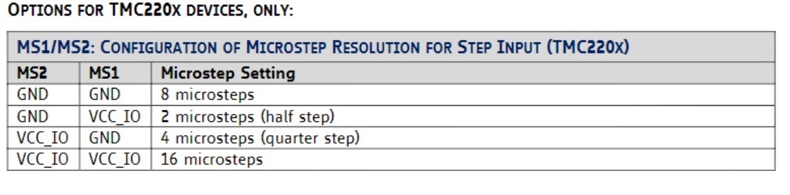
Well, so if I want to change TMC2208 instead A4988 on a SatNOGS original pcb v 1.2 and firmware I must change pinMode to work in 2 microstep??? (cause TMC2208 minimm resolution is 2 microstep)
/Enable Motors/ (A4988) vs (TMC 2208)
pinMode(EN, OUTPUT);
digitalWrite(EN, LOW);
/Step size/
pinMode(MS1, OUTPUT); -------->>> pinMode(MS1, OUTPUT)
digitalWrite(MS1, LOW); //Full step —>>> digitalWrite(MS1, HIGH); // FOR 2 MICROSTEP
IS IT CORRECT?
TMC2208/A4988 TMC2208/A4988 A4988 A4988 TMC2208
MS1 MS2 MS3 Microsteps Microsteps
low low low 1 8
high low low 2 2
low high low 4 4
high high low 8 16
high high high 16 16
AGIS CAN YOU HELP US? …couse if working we will eliminate noise on Satnogs Rotator
Hi,
I am using TMC2208 drivers.
I did not change any of the STANDARD Satnogs software settings.
I did have to reverse 2 wires on each stepper motor to get correct direction(This can be done in software if required).
For microstepping I removed all jumpers(MS1 LOW, MS2 LOW, MS3 LOW, MS3 is not used on TMC2208).
Here is a very helpful link.
Very important is TMC2208 appears upside down compared to A4988, Double check.
I did not and let the smoke out of my 1st couple.
Hope this helps.
Ok guys. A few updates.
I inserted the tmc 2208 drivers in the v1.2 board that previously mounted the A4988, in fact you have to reverse the wires of the motors otherwise it doesn’t work. Then done this they leave. But now the problem of the microstep configuration arises. The TMC2208 drivers apparently do not work in FULL STEP, but start from 1/2 up to 16 microsteps.
Is only pin MS1 defined on the Satnogs stepper motor.ino code which is put in LOW (so it should be GND)?
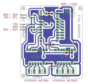
Since the MS2 is not configurable, which from the board in the picture seems to be grounded so the drivers would seem to be working at 8 microsteps, can you confirm my thesis?
How can we set the TMC 2208 to 1/2 microstep in order to still have more torque on the motors than 1/8 and not modify the parameters of the .ino code too much?
In theory from my first tests on the .ino code the variable SPR (step per revoluion) of 200 value should be multiplied by 8 so SPR 1600 better to put the rounding? (SPR 1600L) ?.
In this case, the speed, delay, etc. parameters for motor control must also be greatly increased.
If with the TMC we are able to eliminate the spurious compared to the A988 we greatly improve the reception on the VHF band.
I hope you can help me
IZ5RZR
Sorry to revive an old post, but did you ever get the TMC2208 drivers working correctly with microstepping? I have been going down this same route as you trying to get rid of the noise on 2M and it sure sounds like putting the TMCs in is the solution.
I have been running the TMC’s and also a few older ones like the DRV8825. I’d say there might be even more issues with electrical noise from the silent ones, as they have much higher switching frequencies and a lot of trickery when driving the steppers.
The use of unshielded wires to the steppers is not a good solution imho, but this is what you get usually. Replacing them is usually not super easy either.
Keep them as short as possible, twist them together and put a shielding braid over them will improve these issues. Remember to ground the driver board, shields and motors together properly and avoid ground loops if possible. Having all the components floating or poorly grounded is going to have an impact on EMI for sure.
Some of the first tests with my SuperAntennaz style rotator that runs the silent TMC’s

This one uses the DRV8825

SA2KNG,
Have people had good luck with removing the RFI on 144mhz by better shielding the stepper motors and better grounding as suggested? The amount of RFI is pretty immense for me on this band. I’ve read a few posts with people talking about doing the shielding wiht mix results, but iu2ozh above in this post seems to indicate a massive difference by switching the stepper drivers.
No, I did not pull my spectrum analyzer and prove that the changes I made to were fully characterized (:
It was pretty clear that it was unusable at first, it sometimes was so bad that the serial/usb communication was affected.
I did not operate at 144MHz for this particular setup.
This is also all common electrical design sense, take it or leave it.
SA2KNG,
I apologize if I came off as crass or ungrateful. I do appreciate you taking the time to respond to me in such an old forum about this. I will be trying to implement your suggestions. My only concern was other posts mentioning this was ultimately not good enough for rfi on the 144mhz band.
Some interesting experimenting today.
I tried implementing some of SA2KNG’s suggestions, with mixed results.
I tried replacing the stepper drivers with TMC 2208s, they did not change the amount of RFI on 144mhz at all. The certainly made the rotor mechanically quieter though, the motors are nearly mechanically silent with them at 8 microsteps, and I think they are running cooler too.
While further testing, I removed the stepper motor wires from the controller completely and found the large majority of the noise is still there. There may be some small increase from the stepper motors being attached, but it’s not much if so. So it doesn’t appear to be coming from the stepper motors or stepper motor wires themselves.
I was starting to loose daylight, but I wasn’t able to test with the stepper drivers themselves removed, but perhaps that should be the next step. I’m starting to think though maybe I have a bad ground on the stepper drivers?
Also as IZ5RZR mentions above, the position of the power cable to the rotor can drastically affect the amount of rfi. I did actually try a different power supply as well, a 48V linear power supply, just to try and eliminate potential switching noise. The linear power supply doesn’t change it all either.
That sounds like noise is allowed down the power supply lines.
I’m guessing the AC to DC supply is located away from the rotator in your case.
Is the board minus connected to the rotator chassis ? do note that a long thin wire is bad for this purpose. short and wide is preferred in this case.
These boards does not have proper filtering on the supply lines either, some big caps are usually not enough and will never pass a EMC test.
I would test putting a line filter close to the board to try keep the noise to a as small area as possible. I hade used these FN2010-6-06.
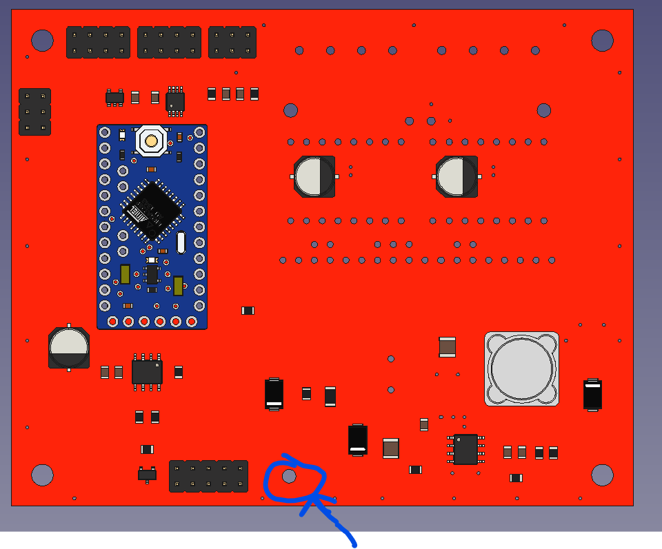
On the 144MHz specific, it might be the AVR 16MHz clock frequency, as it is 9’th overtone. Everything square wave will have loads of signal in the odd overtones.
Maybe holding the reset shows different amplitude in this noise. If this is the case, proper shielding and not allowing that to propagate to any leads that is coming out from the box (chokes, small caps to ground).
I’m guessing the AC to DC supply is located away from the rotator in your case.
Yes, I have the power supply about 50ft away inside my ham shack.
Is the board minus connected to the rotator chassis ? do note that a long thin wire is bad for this purpose. short and wide is preferred in this case.
I have the main ground point on the controller grounded to the enclosure the controller is inside.
The wire isn’t tiny, but it could be larger I suppose.
I would test putting a line filter close to the board to try keep the noise to a as small area as possible. I hade used these FN2010-6-06.
Are recommending putting this Right by where power comes into the controller?
yes, not silly short, but no long loops of wires. twisting them together helps keep the loop area down as well.
Back from the dead after taking a break from this and reporting on tests:
The line filter didn’t make any difference.
I tried a shielded cable for power / serial communication, didn’t make a difference.
I assume by "On the 144MHz specific, it might be the AVR 16MHz clock frequency, as it is 9’th overtone. " we are talking about the Arduino Pro Mini. I tried as suggested and held down the reset button, and this did in fact change the amount of RFI. It increased significantly while being held down.
I tried some chokes on the power coming into the board which didn’t change anything.
When you say “(chokes, small caps to ground).” to try and deal with this, are you thinking caps from the +V coming to the board to ground?