Indeed, as it is missing the adapters ![]() (like the Az has). It was in disassembly phase to pack for Hamvention 2015!
(like the Az has). It was in disassembly phase to pack for Hamvention 2015!
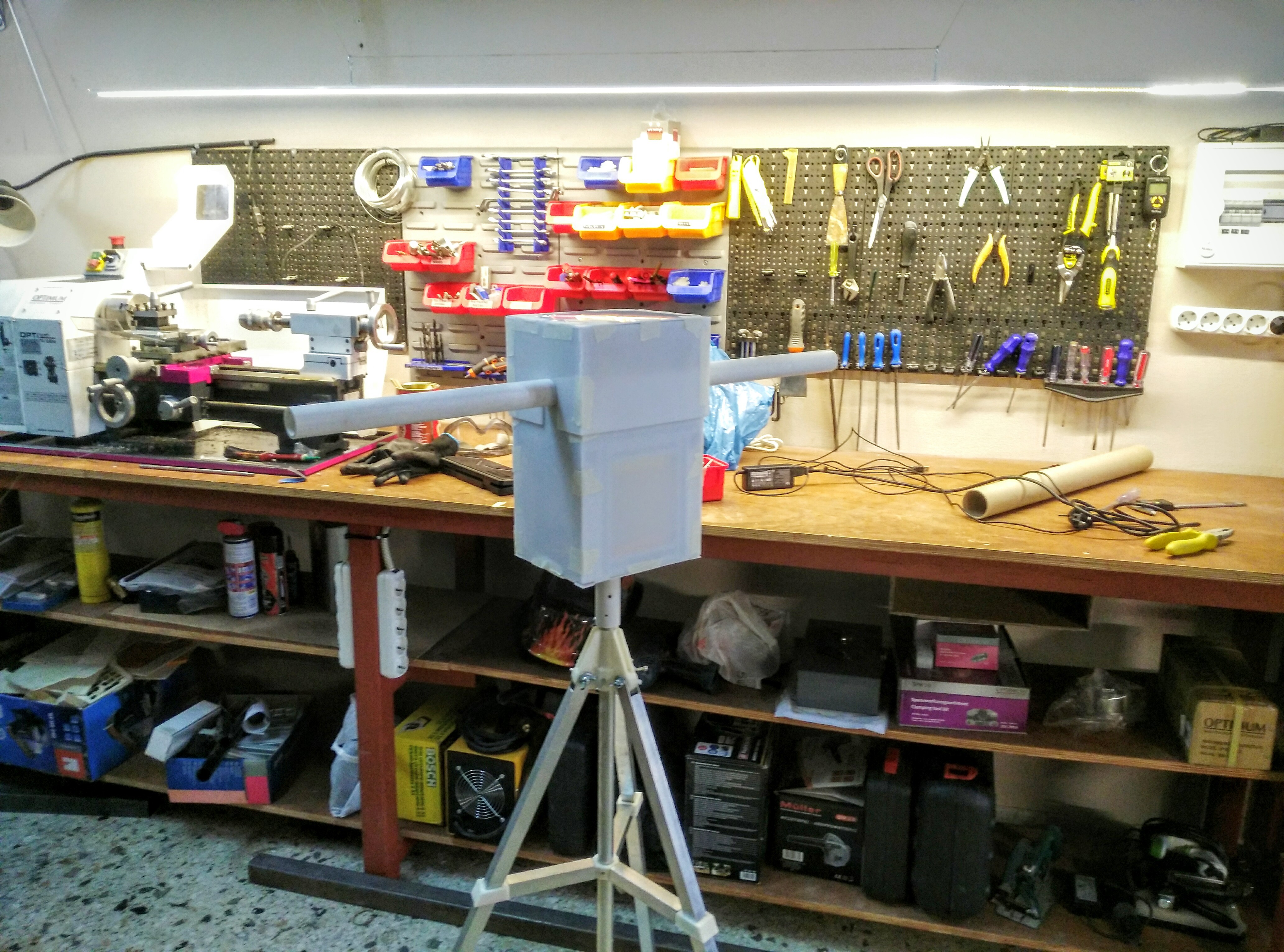
Have you considered using the T-Slotted Profile tube which is used for the frame instead of the PVC used as the cross piece? Then the drive gears can be modified to snugly fit the T-Slotted form. Small round adaptors for the bearings may allow for smaller bearings. I wish I had thought of this when I spoke with you at the Dayton Hamvention, but sometimes the mind works slowly.  The metal shaft may also be more rigid and give more strength to the cross member.
Ed N3OB
This is a very good idea and is very easy to try it, the only concern is you ll have some interference with helical and cross yagi antennas unless they are frond mounted, because of the conductivity of the aluminum.
Hi all!
Is there a draft BOM for v3 yet ??? What about draft assembly instructions? … we’re looking to build v3 for field day. Found the “Master branch” so we’re good on the 3d printed parts … consider us BETA TESTERS! Thanks.
–> Rob, KA2PBT
http://wc2fd.com … the “green shirts”
1 Like
me too. I would much rather test the v3 alpha designs than start from scratch on v2. We need imperial measurements here in imperialist united states though (for our imperialist PVC).
You are welcome to try my adjustments out… Caveat here is that the space between a 1" PVC and the inside of the bearing is just around .4mm, which is the nozzle width of many printers (meaning a very thin spacer wall). See my other thread about what my slicer ended up doing for this but it worked in the end.
(4 parts resized for imperial, not all are tested yet)
Hey, we update the BOM for V3, you can find here.
Stay tuned for the step by step tutorial.
awesome … I’m not seeing motors though ???
We are currently investigating several motor configurations.
The posted bill-of-materials is designed to use the NEMA 17 motors we used in a previous design (v2)
In the future we plan on using DC motors as well with minor changes in our design.
Hi to all, in wich repo can i find the STL from the v3 rotator? i´m confussed and i cant find it.
it´s contains all the parts needed?
Thanks in advance
Mati LU9CBL
Hey!!
The STL and src files for v3 rotator are placed here, and contains all the parts that you need except from waterproof shielding (which is prepared). In the next week we will make a “how to” for v3 rotator in dozuki. Also here is the BOM of v3.
Could you make a FreeCAD assembly file for the EL part of the v3 tracker? (the assemble.fcstd file I see only shows the azimuth tracker)
It’s exactly the same, just rotated 90 degrees. Next week we will have the assembly instructions ready too.
Ah thanks, but it is a different size, correct? (“longer”, L180 instead of L160)
Correct, have you assembled the AZ or EL part of the rotator?
So I notice the motor mount for v3 is round, not necessarily a mount that looks like it would work for the original NEMA 17 motors (and the exploded view that @pierros posted today confirms that).
Did I miss another file/option for a NEMA 17 mount?
This is correct, for the NEMA17 motors we used a ready made mount like this. The mount point on the box is also different. Today we will upload the assembly guide for the DC version maybe the different steps for the stepper one.
Has the “howto” been posted yet? Still learning my way around the community site.
You can check it out (almost complete) here:
1 Like