Hi all, I am building the V3.1 rotator and having a lot of fun. What a great resource!
I have some thoughts and questions.
First, the instructions are all for V3, which is fine as that is the official release. Are there prototype Wiki pages for V3.1 which I can update with any changes or edits? Should we create them if there is not?
V3.1 did not have any imperial parts, so I have recreated those. The parts I have fit over standard white PVC pipe. I used 37mm internal diameter bearings. If anyone else needs the latest imperial parts I could supply. How do we store those, or are they just shared separately?
I built the V2.2 PCB and have a spare if anyone wants one. In fact I built V2.2 because that was what was uploaded to Oshpark and linked from the instructions. I didn’t realize until later that there is a V2.4. I looked at the PCB but I’m unsure what changed. Can anyone summarize it? Do I need to make any changes to the V2.2 PCB?
One final question. I have been using the terminal, but I want to use RS-485 for the actual installation. Do I need to use an RS-485 hat for the PI or is there another way to connect it?
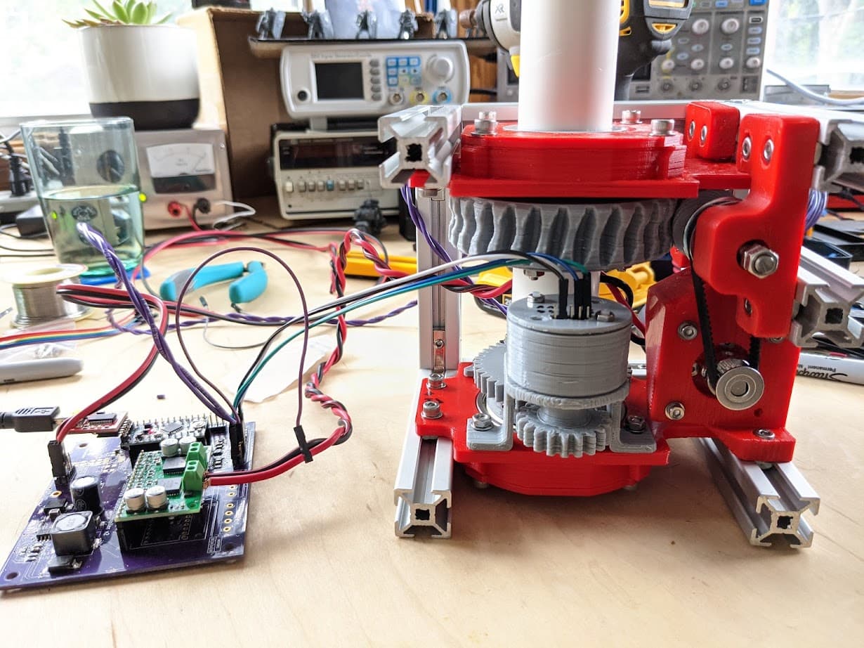
Anyway, everything is working for one axis. I used DC motors. I printed in PETG. I can issue the commands from the terminal and it seems to do the right thing. Which is great. Here it is on the bench:
This is a wiki page for v3 (family) rotator and has instructions for v3.1. v3.1 it has some minor issues.
We have took the decision to not maintain imperial parts. But in v3.1 we have as requirement to reduce them. In wiki page-parts you can add more details about it, is more than welcome!!
I think you can find more details in wiki and in gitlab. The major change it is the addition of a resistor in RS-485.
Thanks for the reply @azisi. Much appreciated. I now have the RS485 connection working and have started on the elevation axis. I’ll see how it progresses and then add some thoughts to the wiki pages if appropriate.
On the PCB, V2.2 already has the resistor. It was changes from 2.2 to 2.4 that I could not figure out. I think they are minor and everything is working, so no big deal.
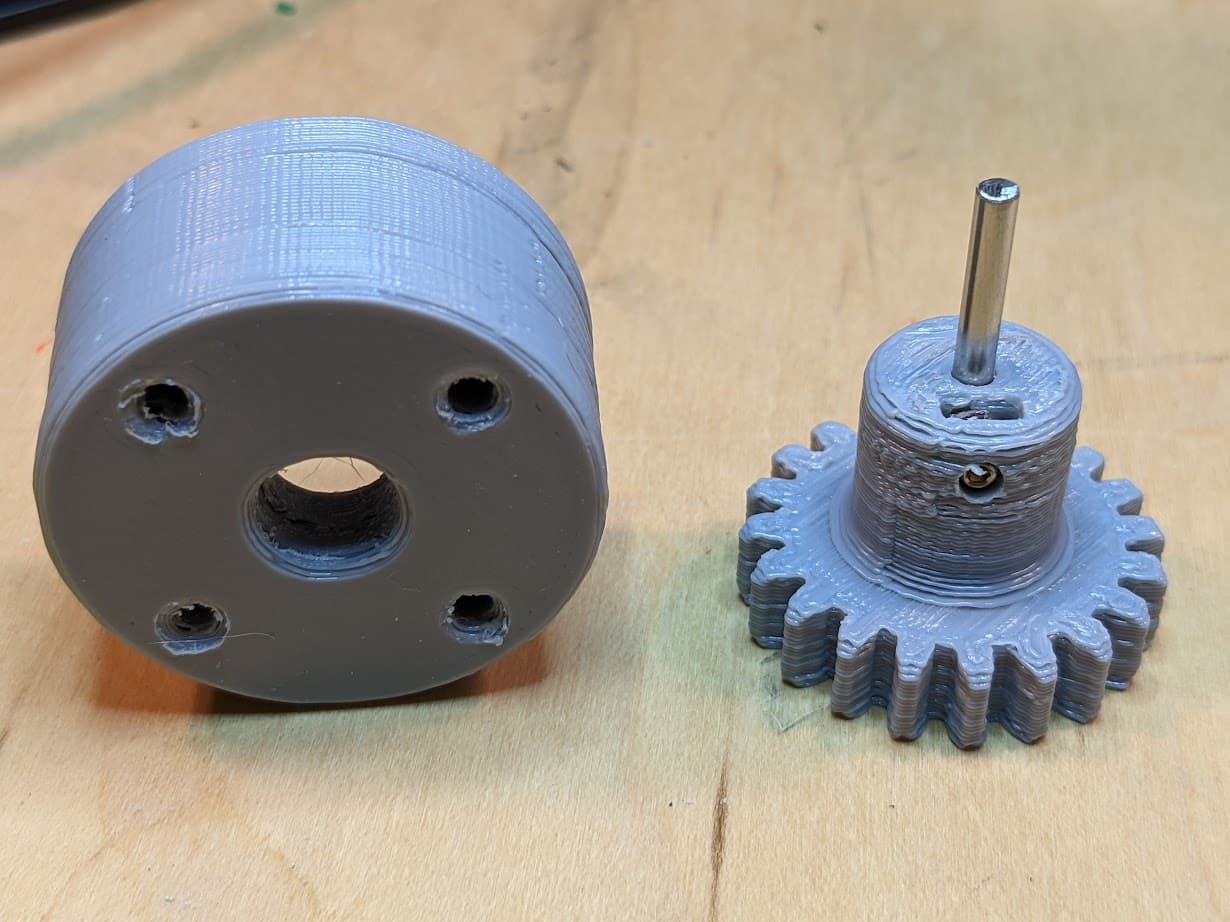
One improvement I have tried to make is with the encoder case. I found it really hard to print because I don’t have an option for support and it has a significant bridge for the top. So I turned it upside down and printed it the other way up. That meant removing the part that inserts into the bracket and extending the spindle on the gear. I’ll write it up as an option or make it available from my gitlab fork of the project.
You can see it here and it was visible in the picture in my first post, working fine for the azimuth axis.
Hi Chris, Im ready to start the process of building the 3.1, Ive seen a couple people demonstrating their 3.1’s on youtube and seen pics, Ive been trying to follow the threads between the 3 and the 3.1 but am struggling. The version 3.0 all makes sense on the official release site but when downloading the zip file on the 3.1 beta page I am having trouble with the information, could you please give me some insight and direction on the best threads to follow, ta
Hi @bridgette, great to hear you are building a rotator. I’m happy to provide any advice I can. I cloned the v3.1 git repos onto my local machine and used the latest files. If you don’t know how to do that I can give detailed instructions.
I was also making a version for 37mm center tubing, so I had to modify a few parts and generate their STL files. I found myself often in FreeCAD tweaking things.
Thanks Chris
Some instructions would be great as Im new in these areas and working locally would be much easier, why the 37mm tubing?, thanks
Regards
Bridgette
One more question everyone, I see numerous pictures of the V3.1 and some of the pics look like the two modules are both symmetrical, then some of the pics look like the bottom module is asymmetrical and the top module symmetrical as per the v3 construction drawings, could someone enlighten me please, thanks
Bree
To have a local copy of the files you need to clone the git repos to your machine. The repos are all here: SatNOGS · GitLab
Specifically you want this for the main files:
This for the controller electronics:
This for the rotator controller:
And this for the software:
There is a download button for each repository, to the right of the screen. That is the easiest way to have a local copy. A slightly better approach is to create a gitlab account, fork each of the repositories, install git on your local machine and then clone them to your local machine. This will allow you to use git to track any changes you make and to potentially submit them in the future as pull requests or a separate fork for others to use. I can send you detailed instructions on how to do that too, if you want. Just let me know what OS you are using.
With them downloaded you can see all of the source files. The STL are not included in the download but it gives you the latest CAD drawings. If you install FreeCAD then you can generate the STL files after making any modifications. I did find that some of the drawings were for an old version of FreeCAD and had to be updated. If you get stuck then ask.
The STL files are in the “Releases” section of each repository. Which you find from the “Deployments” menu on the left hand side. The V3.1 release has almost all of the correct STL files as I remember. Again, if you see any missing or you have difficulty regenerating then just ask and I or someone else can supply a working file.
I used 37mm tubing because that was available here in Canada and 40mm tubing was not. If you can get the 40mm tubing that is a better approach.
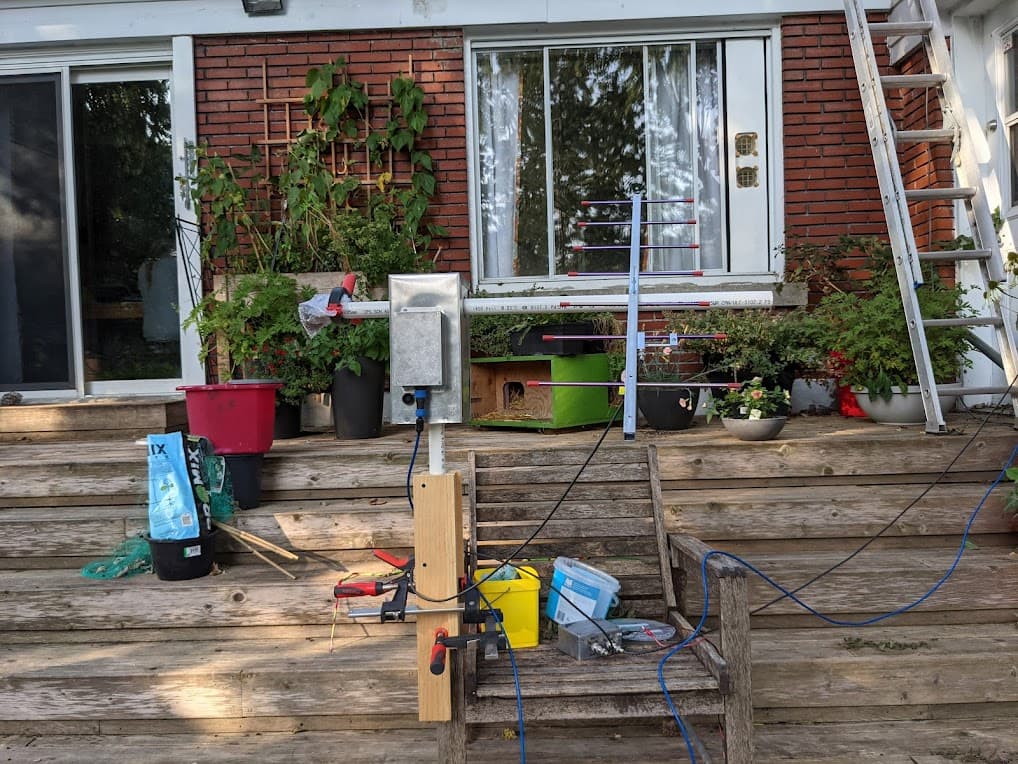
I also deviated from the design and didn’t use CAT5 cables and connectors to route the cables to my electronics box. None of my wires leave the Aluminum housing. I route them in through the back of the electronics housing, which I then waterproofed with a rubber grommet and sealed around the box with silicone. This seems to work well. Here is a pic when it was being tested. There is just one wire that comes out of the box. The wire to the shack:
One other thought. I printed everything in PETG. I didn’t post process any of the parts except to run the worm gear against the main gear with a piece of sandpaper in between. Or at least with the sandpaper being fed through several times. I then lubricated the gear with silicone grease and it runs ok. It is a bit tricky to get everything aligned, but it is manageable.
I am working on building a Satnogs V3 rotor for my university and I was wondering if you would be able to send some photos of your rotor and the wiring connections. Specifically V2.2 PCB controller board, shown in the photo above.
Any help would be greatly appreciated.
Sincerely,
Michael Buchwald
Email: buchwami@clarkson.edu
I missed this until now. Do you still want pictures? I am happy to help in any way. You can send me a direct email if you want. Use: g0kla at arrl dot net