Additional parts like cables for motors and position sensors and connectors
Note: The rotator controller communicates with single board computer via hamlib. An issue of controller is after a few slews we are getting “PULS TIMEOUT MOTOR 2”, any thoughts?
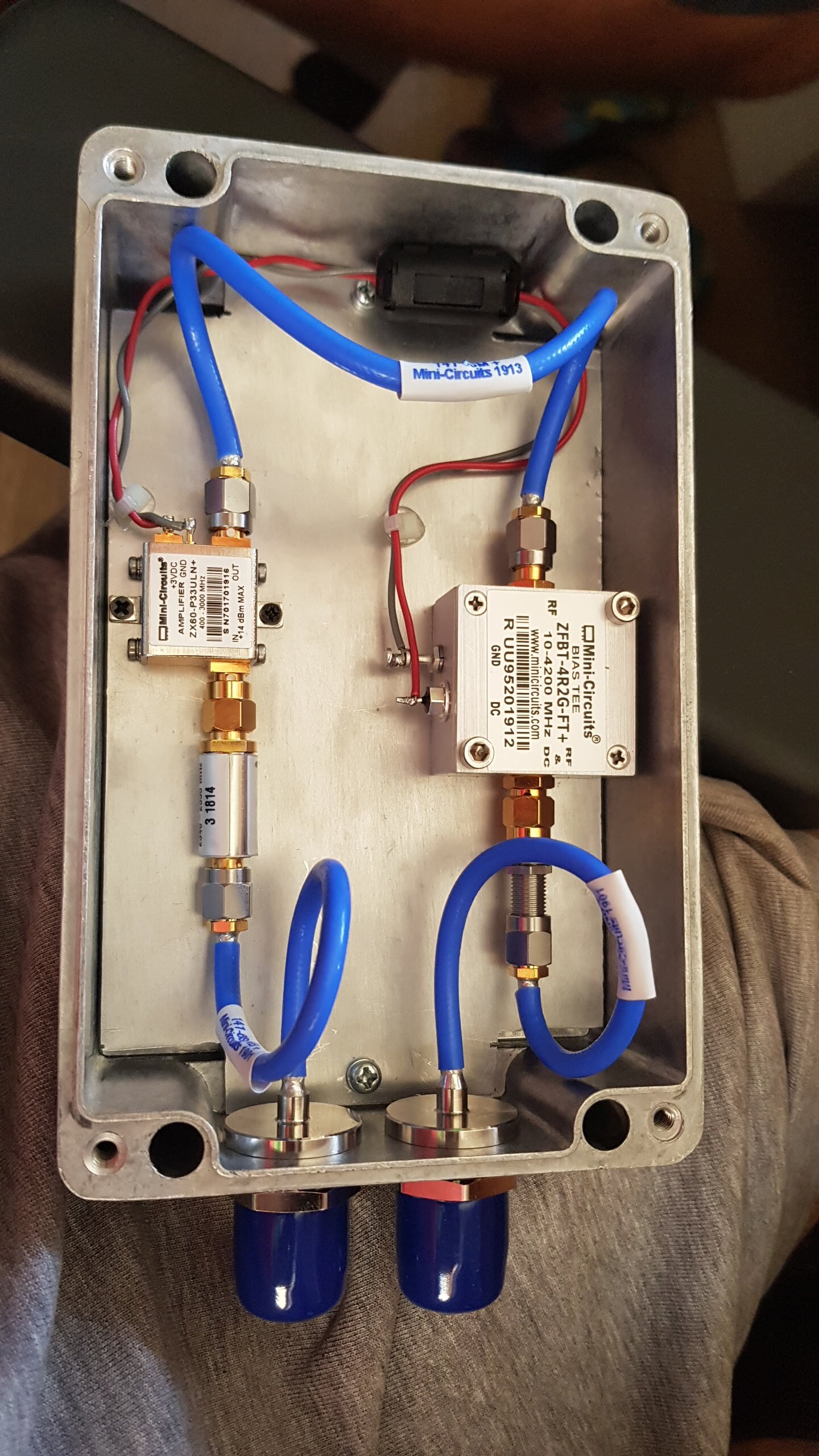
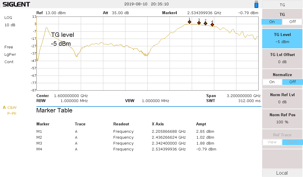
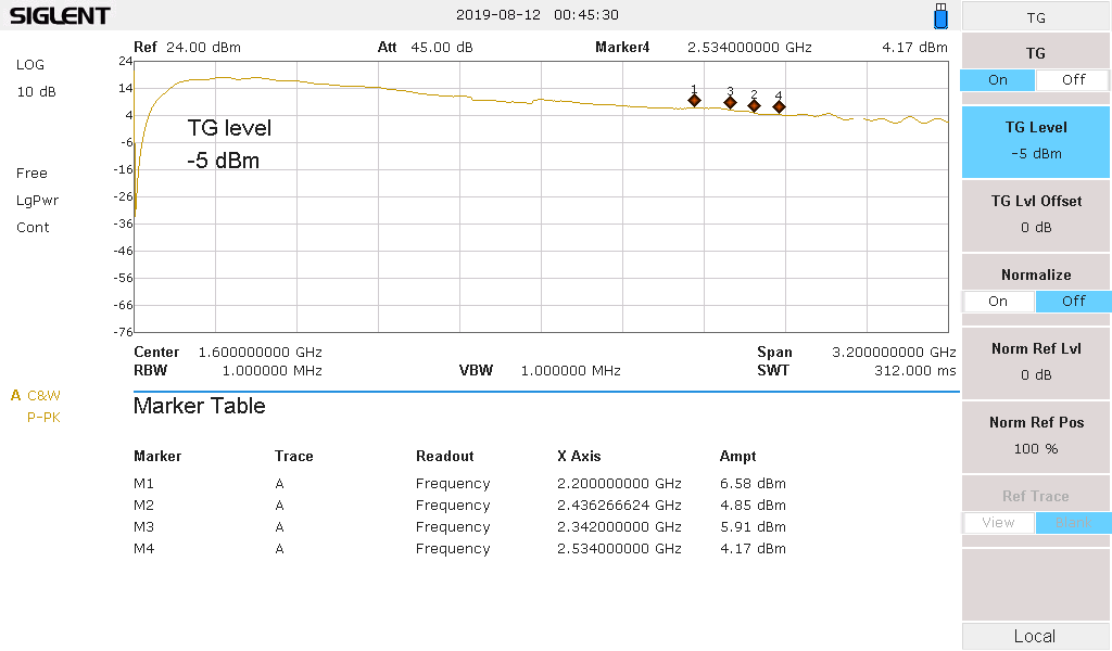
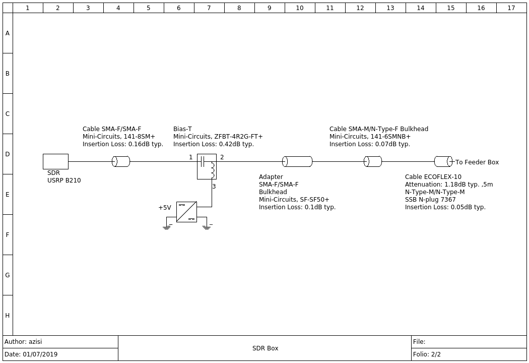
Gain: 7.85dB @ 2.2GHz, measured at the SDR port without using cable ecoflex-10 but a RF cable mini-circuits 141-10NM+. Because the gain of feeder box is low, we measure the gain of LNA only.
The Gain: 11.58dB @ 2.2GHz, which is near to the datasheet value, 12.4dB @ 2.0GHz. So the total losses of the feeder box are: 3.73dB (while the losses which are calculated from diagrams are ~1.3dΒ). Any thought?
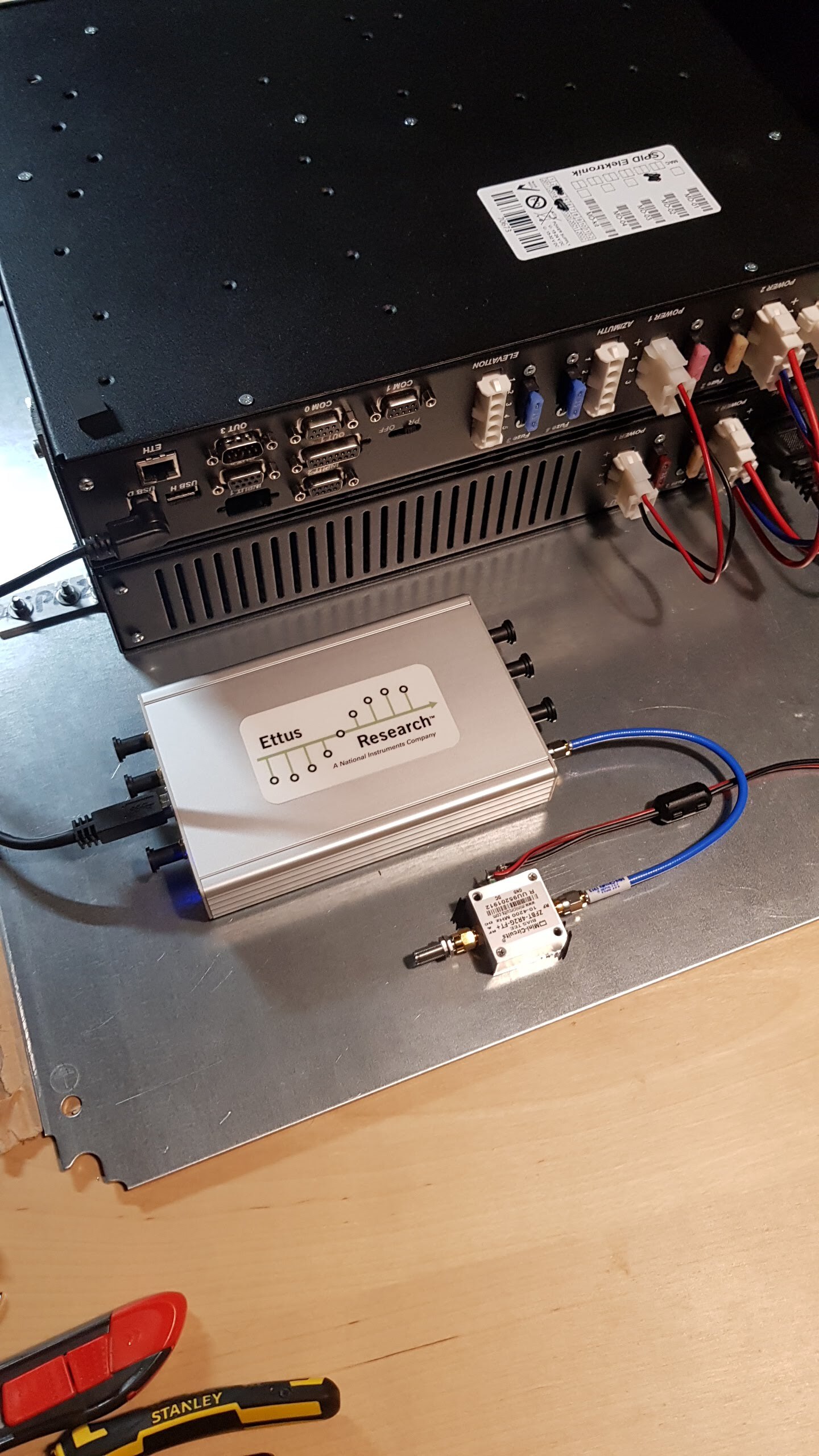
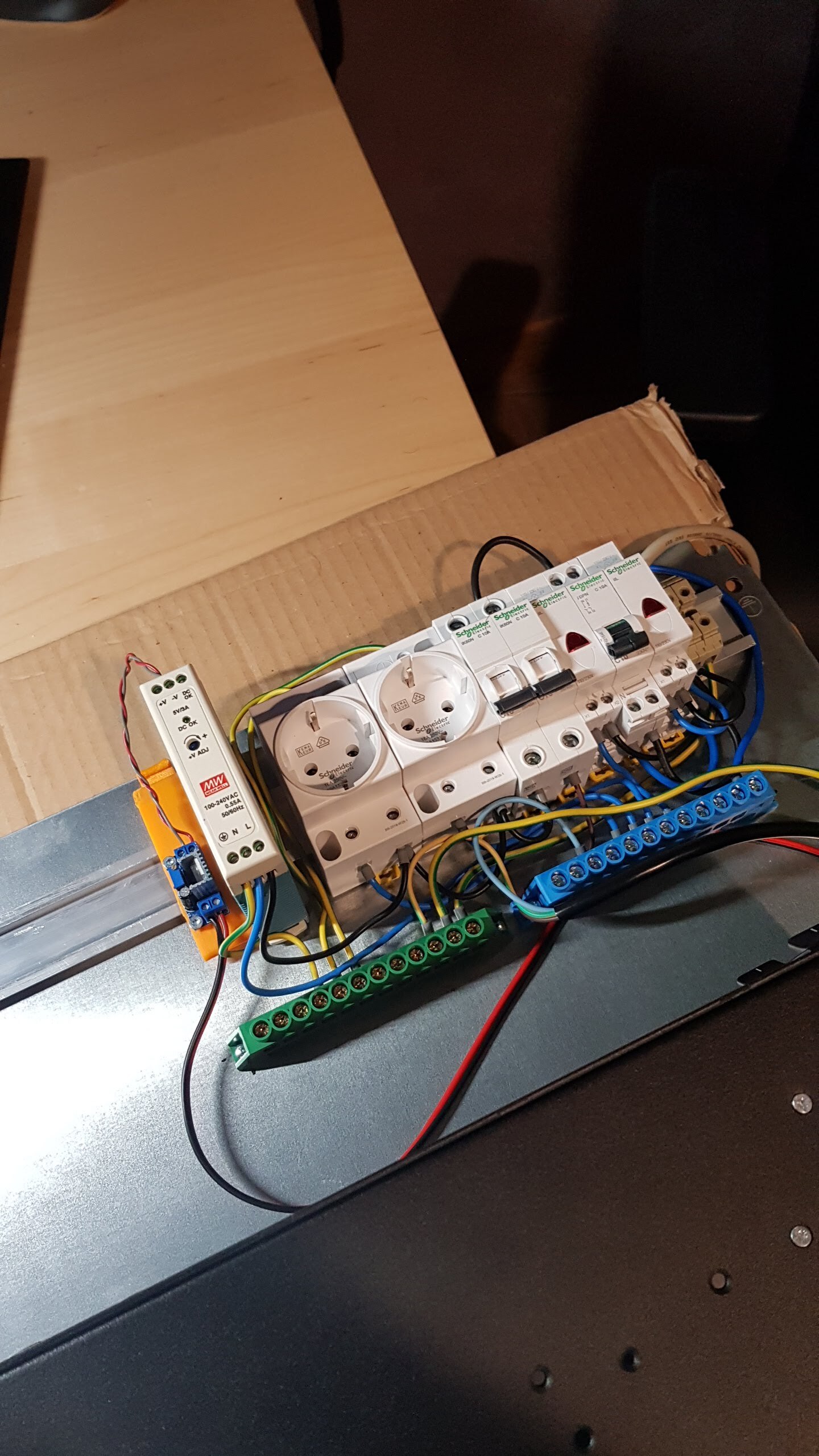
The power supply for the Raspberry pi 3b+ is a Meanwell MDR-20-5. For LNA is used
a LDO LM317 (temporarily, it is needed a better LDO with better power supply ripple rejection) that converts +5V to +3V. The single board computer (Raspberry pi 3b+)
will be placed in DIN rail (@pierros any new photo?).
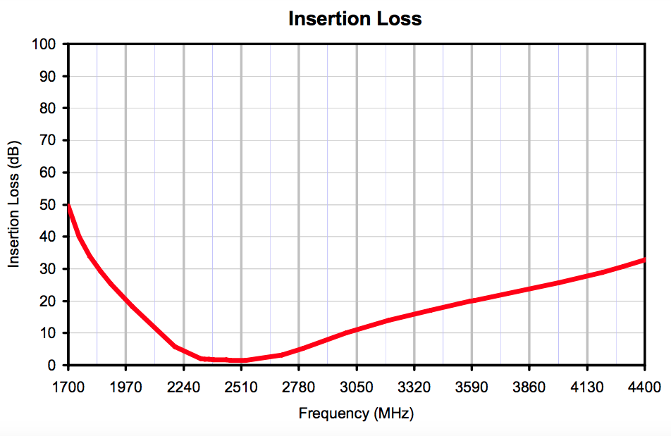
According to the block diagram of the station, the bandpass filter is placed before the low-noise amplifier. Why is that? The BPF has a significant insertion loss of 1.6 dB (minimum; at f_center), as confirmed by the datasheet:
Unless the out-of-band RFI is incredibly significant (unlikely), and the gain of the LNA is very high (~30 dB), which is not, then the LNA should be placed before the BPF and not vice versa.
Not sure where I should inform people about this but the MD-02 rotator controller has a design flaw that everyone should consider if using it actively. The controller applies 24V to motor wires/coils when the controller is powered off or stand-by. The potential stays same on both wires so the motor won’t turn BUT because the motor’s copper coils are in higher potential than the grounded body of the motor, a thin film of water on the inner surfaces of the motor coil will make the current run. This causes the copper to corrode away from the motor until no copper is left and the motor’s body is full of black copper oxide. Powered motor cables can also cause unwanted dish rotation when one of the cables gets accidentally shorted to ground! Moisture can get in to the motor from a hole in the bottom of motor. The hole is there to let condensation water out so it shouldn’t be plugged but this hole also let’s the moisture in…
I’m not sure what is the best way to solve the issue but we decided to implement our own controller with STM32 and stock PWM motor drivers.
The noise factor, F = F1 + (F2-1)/G1 and Noise Figure, NF(dB)=10*log(F) is:
BPF+LNA: 2.1dB
LNA+BPF: 0.58dB
So, you are right. But the position of BPF it depends on the noise of the environment where the ground station is placed. For example in Athens, a noisy environment, the BPF before the LNA is necessary to reduce the noise in input of LNA (due to inter-modulation in output). This S-band ground station is placed in Kalamata, so we must change the position of LNA and BPF (LNA+BPF). Thanks for your feedback!!