I am currently building my rotator (version 3.1). Now that the frame is assembled, I noticed that there are no instructions on how to transfer the weight onto the vertical axis. If nothing additional is done, the weight seems to be hinged on the 3D printed parts with the tiny M3 set screws. Those won’t be able to support the weight of the rotator including antennas. Could someone shed some light on this for me? I am assuming that a flange ball bearing should be placed on the bottom frame side, but I couldn’t find any pictures confirming this.
2 Likes
Hey! Take a look in the wiki, and let me know what you mean (with part numbers), because i couldn’t understand your question.
Thanks, I already looked at those.
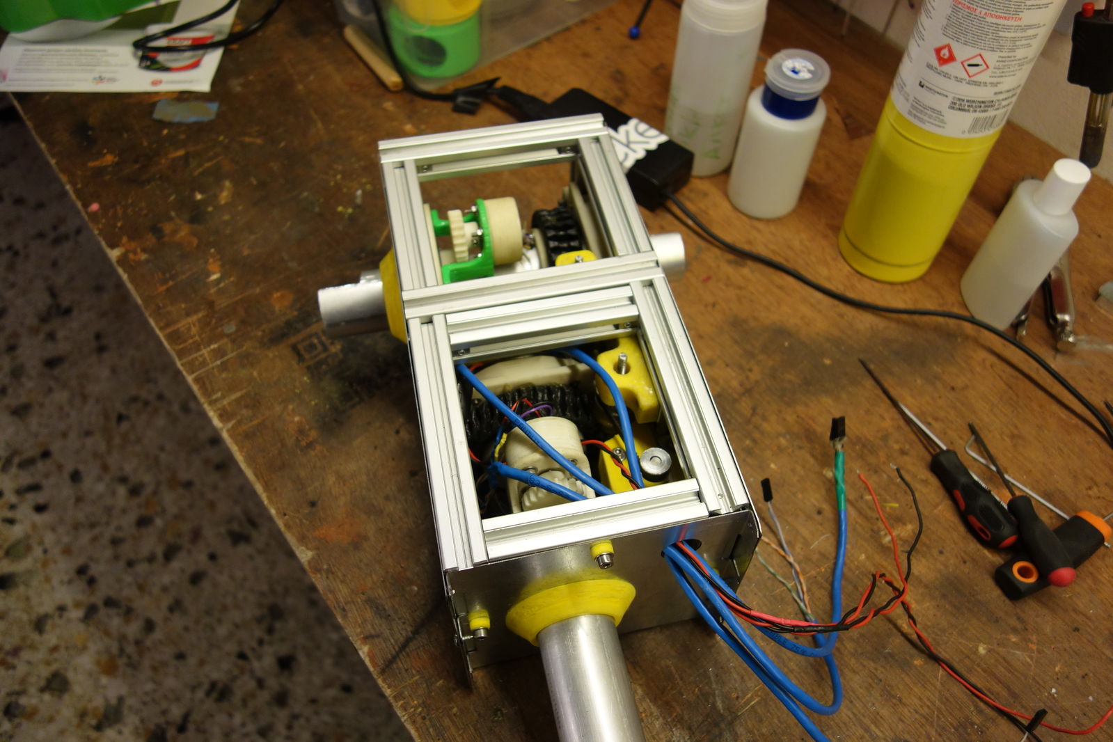
See this image for instance - there is a yellow ring at the very bottom of the mount - this does not look like it is carrying any weight though.
I am assuming that instead of this ring we would have to mount something like this, which is then bolted onto the bottom side of the azimuth frame.
The total weight of the assembly is gonna be pretty substantial and I cannot see how it would be carried by the few 3D prints, that actually make contact with the vertical axis and could transfer weight. If I am missing something and you can point me to the parts that hold the weight on the vertical axis mount, that would be super helpful.
From this picture i understand that assembly #10 and assembly of #2 and #3 is used to take all vertical load of the rotator, which is maximum ~10kg.
The A1020-1 takes this load.
If you have any problem open an issue in rotator repository. Also if you want to propose a better solution i am happy to see your merge request. 
2 Likes
Sorry, I was actually building v3.0.1. That probably caused the confusion.
Since I already printed all the parts, I choose to use 3x the axis_spacer_collar stacked on top of each other. This looks to be substantial enough to be able to take the load now.