Just finished wrapping my head around the rotator hardware, sourcing, instructions, etc., and now I’m digging into the rotator controller files. I’m not really sure how to approach the controller, so I have a few questions!
I’m planning on using the stepper motors -
Does this mean I can ignore all the “encoder” files?
Do I still need to build the stepper motor drivers (or was this part of an older version)?
Do I need a PCB for the stepper motor drivers?
Where can I find that design?
Lastly, where can I find a list of components for these PCBs (including Arduino and ICs)?
Are there instructions or a map of which components to solder in which place?
Are there any wiring diagrams?
Thank you! I’ve learned a lot reading through older posts, but I’ve still got a lot to learn!
There are some good questions in there. I’ll have a go at answering them. A stepper motor rotator is the same as mine so I’ll describe what I have done and hopefully that will help. You need a controller to run the motors (either DC motors or steppers). It is a small microprocessor from the arduino family that doesn’t have the power to drive the motors on their own. Two additional boards are used to do the heavy work that are plugged into the headers.
Other than that there are some SMD components that help make the circuit run smoothly. You will find the BOM and the KiCAD schematics and board layout files here.
The encoders are for the DC motor (I think) and the end stop indicators are for the stepper motors. That way the controller knows where its pointing.
i am on building my first station at the moment too
But i did not find any information regarding the end-stop-switch?!
All i found was the picture and the hand crafted wiring diagram in the documentation in the wiki.
Can you provide a part number or something like that, so i know what switch does fit in the frame and is known to work with the controller board?
TIA und best regards,
Sebastian
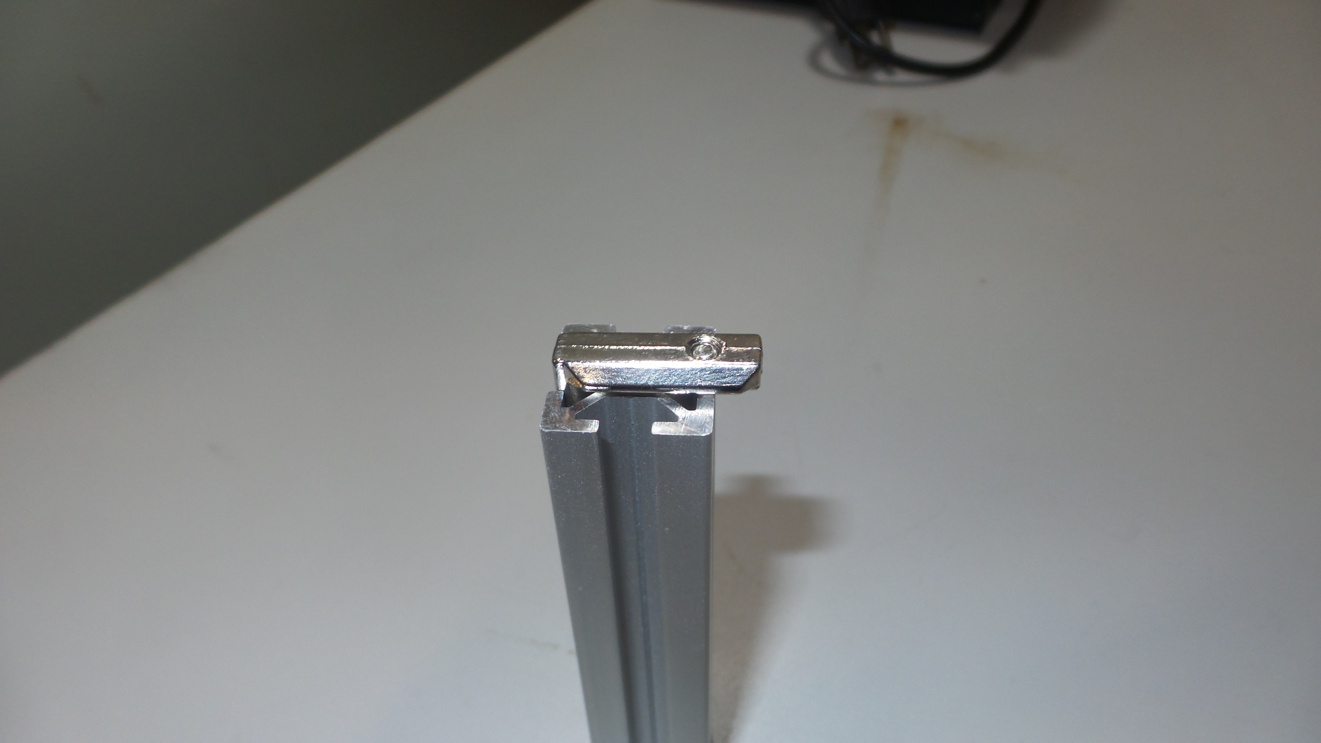
PS: How can i contribute to the OHAI? I would love to add some little things like the reason for the asymmetric hidden corner connectors or tipps regarding the endswitch when i know more about it
I’m in the process of building a imperial version of the 3.1 using stepper motors right now. Got the frame, motors, etc all mounted, working on wiring and controller now (I burned up my arduino, was using a 3v version instead of 5v version)
So far it’s coming together pretty good. The hidden corner pieces I got was longer than what’s shown in the wiki pictures, but I was able to fix that by using the outside on one piece and inside on the other.
I did have to modify some parts to fit imperial PVC (using 1"). I actually created a 40mm bearing adapter that the pvc slides into and you can lock it down using 3mm nuts and set screws.
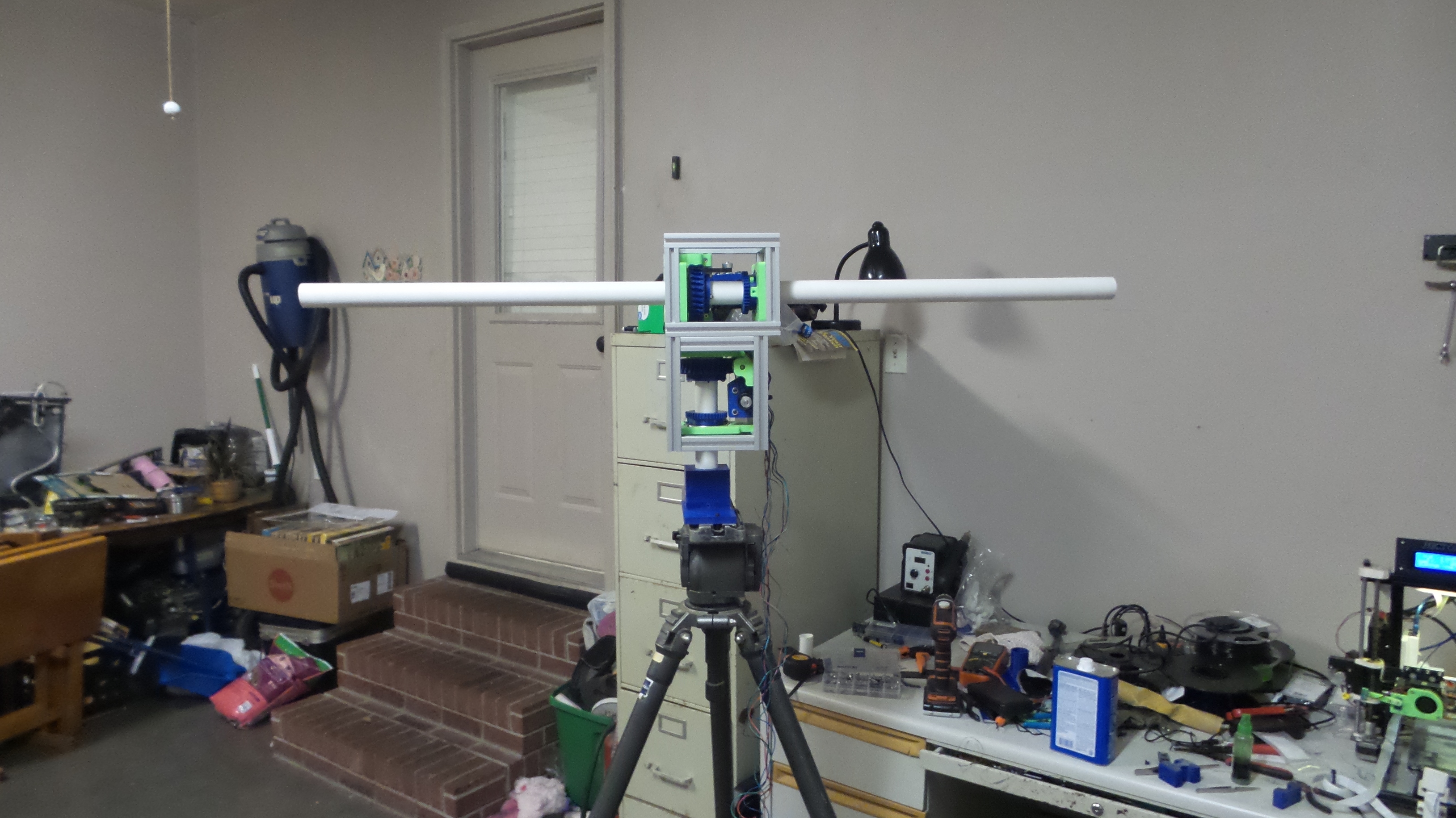
Yeah it’s the final place, it’s an old tripod for a 80’s video camcorder I had in the attic I got from some yard sale, I just printed a adapter plate for it that would fit the 1" pvc and some set screws.
Should have my new arduino 5v today (burned up the 3.3v chip since I didn’t realize I needed to use the 5v version), think I’m going to use a buck converter to supply the 5v power so I don’t burn this one up as well instead of using the raw pin that would convert the 12v down. Regulators aren’t the best on those. See http://westsideelectronics.com/blew-up-a-cheap-arduino-pro-mini-clone/
Also in the process of putting the 1" pvc into things, I managed to bend a limit/end-stop switch. Got a 20 pack on order from amazon to replace that lol.
In the process now of building a pvc antenna for it. Plan on doing a dual band 2m/70cm antenna, but not sure if I should mount both types of elements via horizontal polarity or vertical polarity. Anyone got any suggestions? From videos I’ve seen, most people mounting things with vertical polarization.