I’ve put a couple of images in the wiki now should it should make sense. I’ll let the dust settle a bit and go back in a few day’s and make sure it still makes sense
What changes to the current (3.1+) STLs would I need to build the same machine with NEMA 17 steppers? I have lots of 3D printer building parts and want to use what I have. I think the old ones are gone off the site. I’d be happy to host a set if you have them.
Hello,
A bit of new construction of the V3.1 rotor design is great and simple for a good handyman, a big thanks to the contributors for the changes made soon another video for the tests with rs link 485.
Rémy.
Very good job.
I Think that after rotator is finish you must shield pcb because the stepper motor RF noise is very strong. A hammond metallic box or similar is required for eliminate RF noise
Help … the v3.1 rotor works well, except the optical endstops, I did the tests on all the ports endstop of the shield board, it does not work, I put LOW in the line (#define DEFAULT_HOME_STATE LOW // endstops do not work, does anyone have an idea?
I don’t know what signal your optical end stops are using, I modified my sketch for standard mechanical switches, and the CNC Shield uses ground has a signal for its and stop switches I believe, which is why I had to change it from high to low. Have you tried setting it too high to see if it works?
Hello, soon the final operation, I extended the rotor down to incorporate the following elements (12v outlets and usb / rs485 converter) the tests will be done with PstRotator.
Rémy.
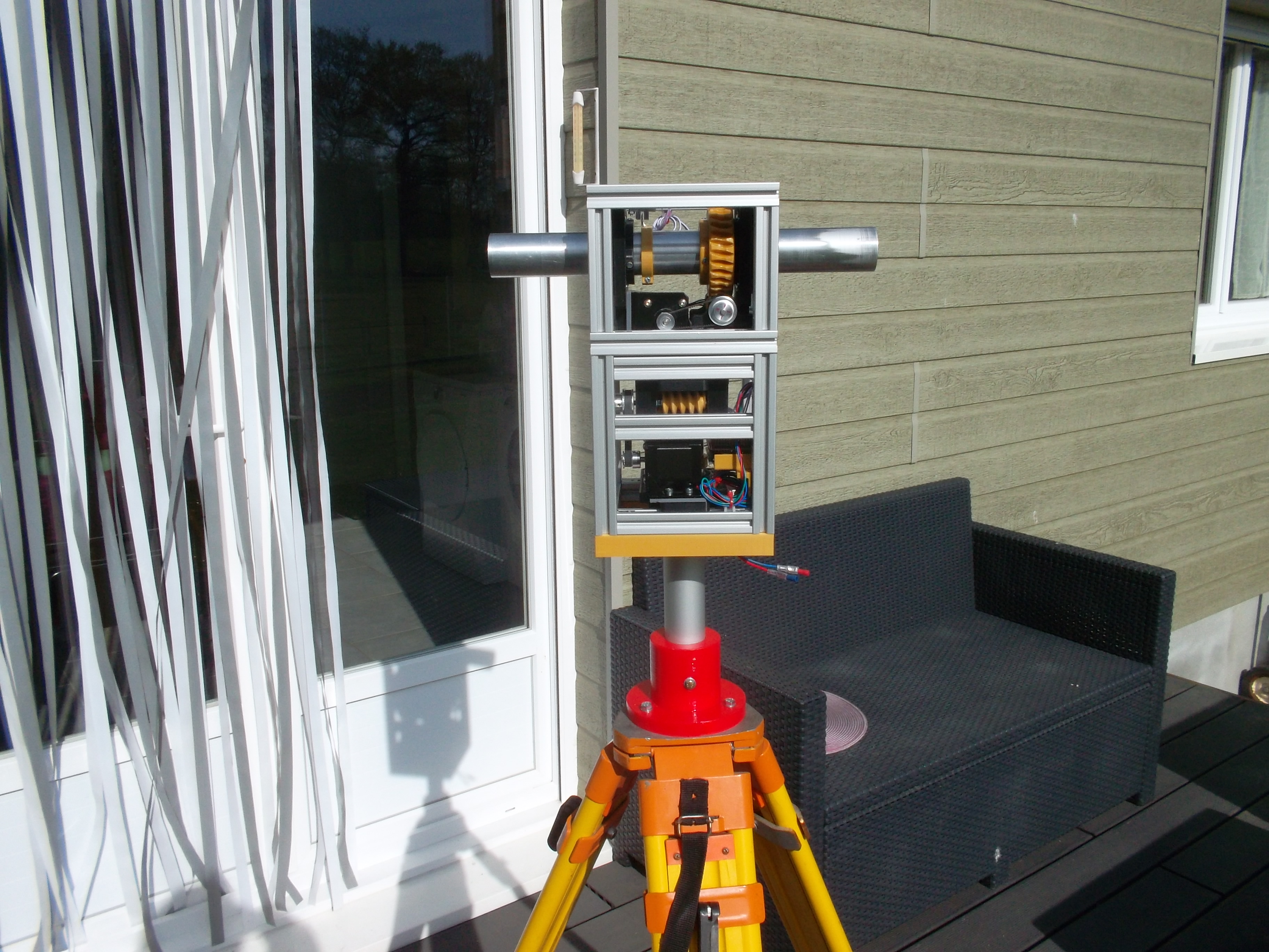
Been awhile since I’ve posted on my thread! I have been playing around with HRPT this weekend and the Satnogs rotator with modified 2.4ghz dish, and have had great success with Tysonpower’s free script. I plan on trying XHRPT from USA-Satcom next. the rotator is working perfectly with gpredict. I havent completely weatherproofed it to stay outside yet, it can bet setup in a few minutes, the rotator drops onto the tripod, and the satellite drops onto the screws, then the counterweight. it’s hacked together but it works great and took minimal time. here’s some pictures from today!
well, I haven’t fixed the meridian pass issue yet,and it’s causing problems. I’m going to start looking into how to implement other fixes… from my initial research, it’s not a quick ‘cut and paste’ of code. the only one that functions with my setup seems to require some buttons installed in the arduino to zero out the az/el… the meridian pass flip issue just ruined a perfect 85degree NOAA19 HRPT pass… missing a big slice out of the middle of an otherwise perfect image. I’m going to start reading the meridian pass threads and try to get it working for my rotator… can’t have this happen again!
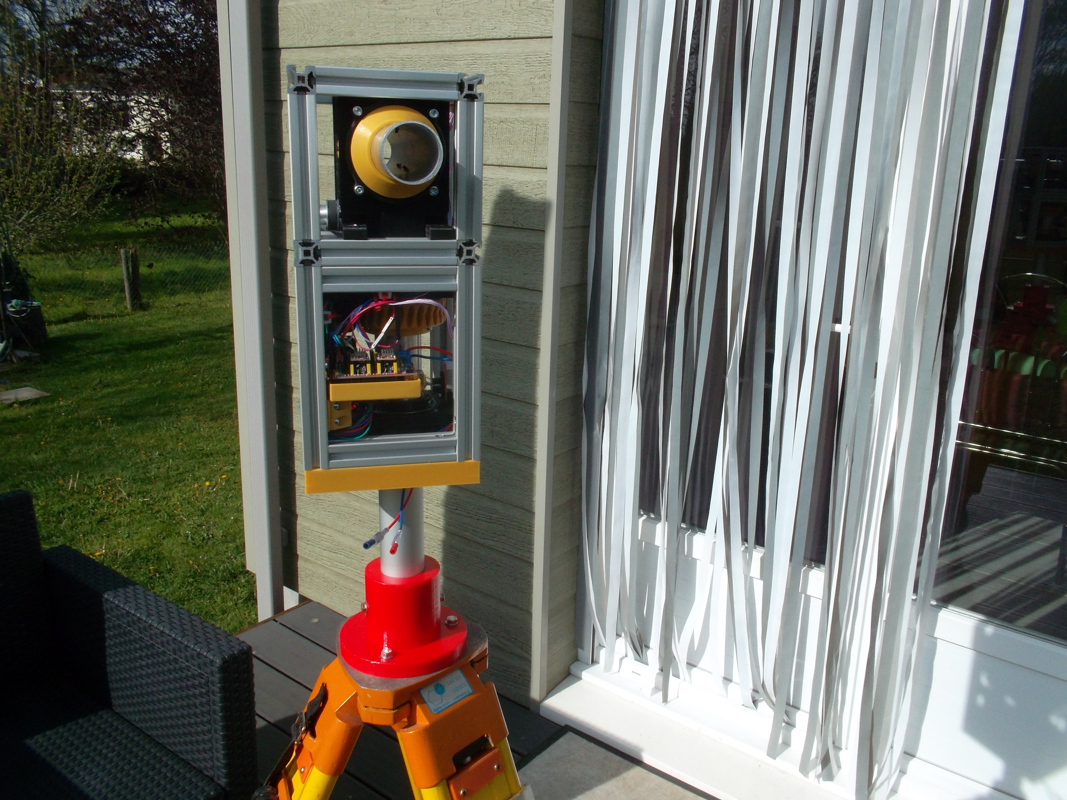
My rotator is now weather tested! it has been outside, 24/7 for the past two weeks, over numerous heavy rainstorms, fully functioning and 100% powered the entire time.
here are some pictures of my waterproofness. I have changed the satellite to a normal position instead of the skew in the pictures as well and the signal strength has greatly improved.
I have been tracking HRPT satellites with great success, very strong consistent signal, even from the birds that are a bit harder to track like FengYuns or MetOps.
I send the rotator back to the GOES 16 position for HRIT/LRIT when not tracking usually where it keeps the dish pointed well enough to maintain less than 200 viterbi rate error
I spent a lot of time this afternoon trying both Meridian Pass scripts… one I got communicating with Gpredict, and successfully controlling the motor… but it would randomly do unexpected things as I was testing it manually.