Hi everyone! So in the past 2 weeks we have developed our Ground Station 3172 - USM_SAD. We are using Cross Yagi Antenna 430-440MHz. The rotator is working fine rotating accurately to the destined azimuth and elevation.
The connection described as below:
Yagi Antenna- Coax Cable 5 meter- RF Switch (HMC349)- LNA 20dB- RTL-SDR 32dB.
We have conducted test as strong signal in near-field test the signal is observable. But for satellite signal we still have not be able to capture any yet.
We are still looking for the potential problem that may affect this and hoping the help from the community
The local test with a strong signal (fm handheld I guess?) will just get into the sdr no matter what you have connected, and the lack of signal clearly indicates a break in the rx chain.
I have also looked at those RF switches and have a few on my desk, I have not used them on any antennas yet. I would say as Jan did, eliminate all sources of error, hook it straight up and verify that it works, then add components.
The X-yagis that come with a matching kit to allow both polarizations to be connected to achieve R-/LHCP should be connected with both. Or the feed directly to one of the driven elements.
Looking at the described setup: Yagi Antenna- Coax Cable 5 meter- RF Switch (HMC349)- LNA 20dB- RTL-SDR 32dB.
~5 meter coax is what I would use from antenna to preamp in such a setup, pretty much what I have here:
What is the purpose of the RF switch? To switch to a transmitter?
I would also consider you try a higher gain setting on the RTL SDR if nothing else works after ensuring the LNA is amplifying properly. Checking that the Coax is good could also be helpful.
The antenna from R+/LHCP kit - Coax Cable 8 meters to the box down there - RF Switch - LNA - RTLSDR - Rpi4
There is a 5V PSU inside the box that powers up the LNA with a boost regulator. @ENSFNM yes the RF switch is to transmit command to our SPACEANT-D (98995) satellite.
Sorry for the late update, we have tried bypassing the RF Switch and only connect to the Vertical element of the Yagi bypass the RHCP kit as well eliminating all the source of error (as this gives the best SWR apparently in our setup). So the connection is Yagi V element - RTLSDR and we got this observation with some other signal : SatNOGS Network - Observation 8749034. Then we tried reconnect back the LNA with proper source of power with less ripple Yagi Vertical Element - LNA - RTLSDR -Rpi4 and it manages to capture some satellite signal: SatNOGS Network - Observation 8749162 . Then we tried to properly ground the LNA and the observation got better : SatNOGS Network - Observation 8749253
Now our ground station can start to capture signal from satellite but we are still finding ways to make the observation signal more stronger and reduce the noise level.
This can be done, but all the noise that is not seriously filtered will end up in the LNA and raise the noise floor and introduce spurs and whatnot. If possible, dedicate a small linear supply to the LNA.
Where is the LNA located, and what type ? any filters ?
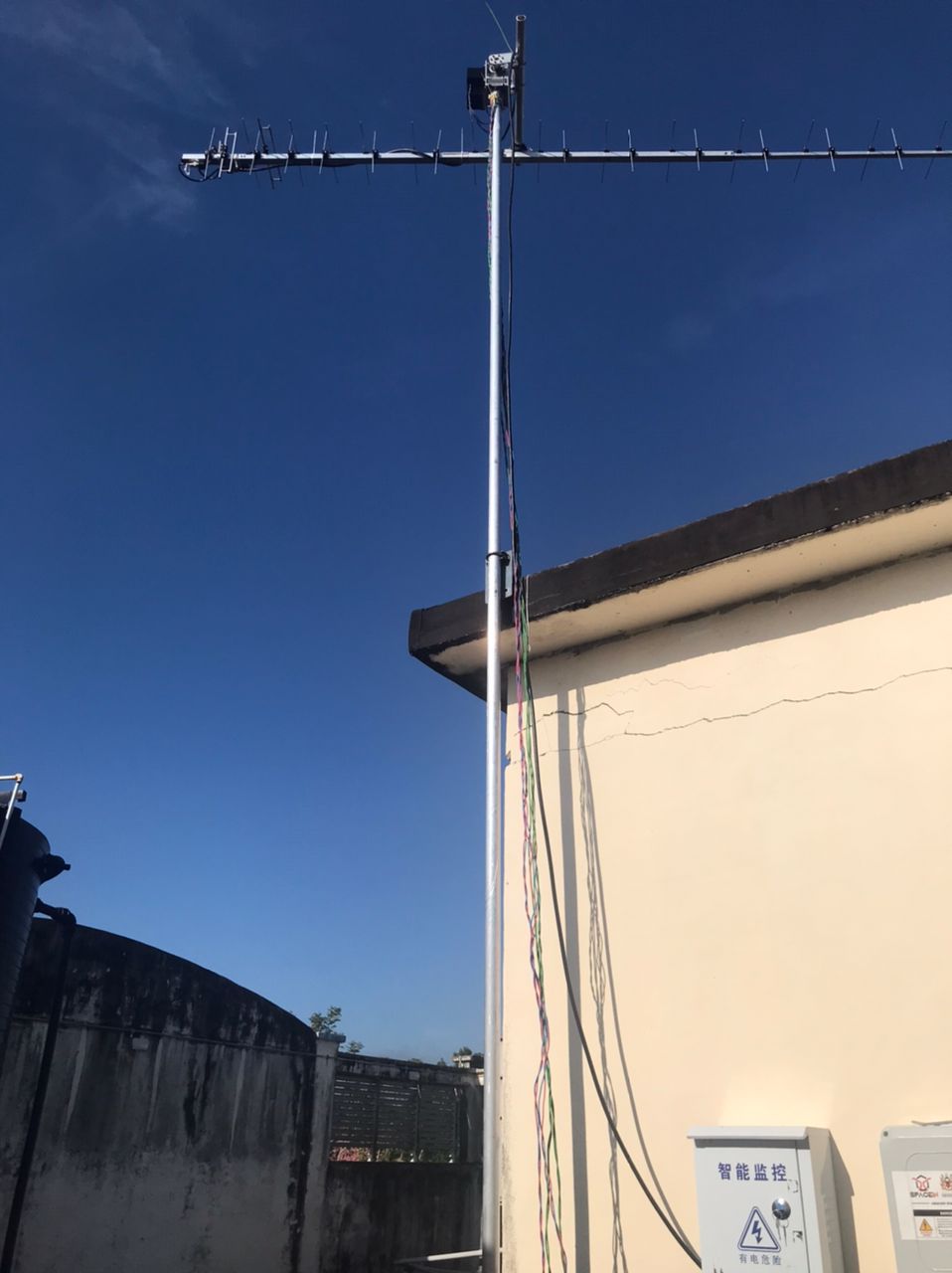
From the image I cannot see it up at the antenna, is it located in the box down on the wall ?
From my own and others experience, this is continuous work (: It’s also pretty sweet when you make a small change that makes a huge difference!
Best of luck and hope you find as much pleasure as myself and other station operators do.
The power management for the LNA has significantly reduce the noise floor for our observation. But the noise is still there and we really suspect it is because of the LNA we are using (as we tried bypass the LNA and the observation aren’t noisy as when we plug the LNA)
The LNA is located inside the metal box down there as seen in the picture below
The LNA is a cheap wideband 1MHz - 4GHz, cannot find the LNA based =D
Do you have any recommended LNA that suits our 430-440MHz application and any advise regarding our setup?
That is so true, this continuous progress is either pleasure or sighs XD.
Thankyou!
It should really be as close to the antenna feedpoint as possible. If using a good low loss cable you can place it close to the rotator as well. If you put it close to the receiver then the signal has already been lost in the cable and cannot be recovered by any lna.
Filtered lna is preferable, but that also depends on how it’s built. The ones using SAW filter (has high loss) usually puts the filter after the lna, but that means the lna itself can amplify closeby signals and also distort the frequencies of interest. While big EME models and mast preamps have a low loss bandpass filter in front of the lna instead.
I would say a decent mast preamp is a very safe bet but can be a bit expensive. If you go for one of the small modules with sma connectors you still need to build a case for it and N-SMA connectors etc. Remember that all adapters are a source of error, stuff with short cables (pigtails) can be more reliable in this case.
Regarding the LNA itself I have my favourite PGA-103+ but there’s the PSA4-5043+ and a bunch more out there as well.