as noob with not a lot of budget I decided to investigate a bit in a LNA cheap solution.
Some of you checked my signals received until yesterday from my GS (CH-CR), and I got the suggestion to put an LNA close to the dipole.
I’d say remove even more. for UHF with LNA something like 20-30 would be high in my book.
Looking at the live spectrum at 145 or 435 MHz and increasing the gain until you start to see the entire noise floor flood with “signals”, you know that is the upper limit. You should run it below that, way below.
for my 430 - 440 waterfall experiment with Logper antenna, 434 Mhz filter and same type of LNA I ended up with 9 dB gain for the rtl-sdr , But as Daniel suggested, testing the gain with some visual sdr application would be the best
@Calligula… I use a new SD card with a copy of Luigi Cruz’s PiSDR image burned onto it. It has GQRX, which is a very simple SDR program and works with most SDR’s. It uses the GUI so add a temp keyboard and mouse while testing…and then follow SA2KNG’s method.
When you have the best gain values…simply pop the SatNOGS SD card back in and set the new gain values…very simple.
The SatNOGS Wiki has a section about ‘Setting the gain’…it uses a SoapySDR-server which is too hard to get working. It is simpler to just use the PiSDR image and GQRX then follow instructions for setting the gain.
I’m not sure how to interpret… good or bad?
there are those straight horizontal lines in the waterfall… these where not there before the LNA installation… I’ve the feeling that something is wrong…
@calliigula I notice that you have some wideband background noise on your signal passes. This can sometimes be due to strong closeby signals…perhaps FM broadcast stations or similar.
Start by trying to fit a Broadcast Band Stop filter before the LNA. I always use a HPF on my systems (300MHz on UHF and I think it is about 120MHz cutoff on VHF)…
Let us all know if it improves the situation…it helps other users with similar problems.
Btw… how do you see that there is wideband background noise? (sorry I’m curious to understand how to interpret data and waterfall… I’m a noob)
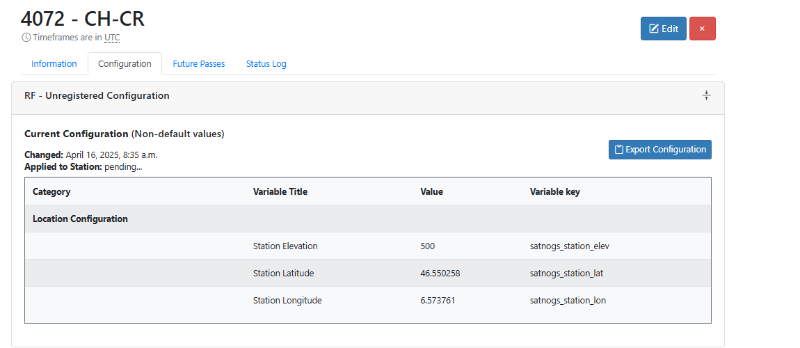
btw… Am I supposed to see that “pending” in the GS configuration?
@calligua Stephano…Firstly the AM filter you identified is a High-Pass Filter that cuts in at 1.6MHz…this will let all the FM Broadcast stations pass…so it is not suitable.
This is where you have to make some decisions on what frequencies you want to receive. I see from your observations that you are receiving VHF NOAA satellite around 136-138 MHz as well as UHF satellites like the ISS on 437.8MHz.
The second filter you identified is a Band-Pass Filter 137-175MHz so it would be on the bottom edge for NOAA sats and ok for Amateur satellites around 146MHz. But it would block signals for UHF like the ISS and most CubeSats. It would also block the FM Broadcast band. I think I would avoid that.
I note with interest that the UHF ISS observations look fairly clean and the VHF NOAA observations are the ones with the interference. This suggests the interference is lower in frequency and the most likely culpret is FM Broadcast stations between 88-108MHz.
If you want to receive both VHF and UHF on the one SDR I would start by putting in a FM Broadcast Band Band-Stop Filter (88-108MHz Stop-Band). This kills the FM Broadcast band signals, will pass signals below 88MHz and above 108MHz so your VHF NOAA and UHF CubeSats would be ok.
I personally use separate SDR’s for VHF and UHF. For the VHF I use a MiniCircuits SHP-150+ (133-1000MHz) and for the UHF I use the MiniCircuts SHF-400+ (395-3200MHz). They are not cheap but they are good quality.
So, start with the FM Broadcast Band-Stop and then go further if required. Note the Filter should be before the LNA.
It is time you look at an other antenna, maybe it is an idea to build this combination DK7ZB yagi and place/connect it at an angle of 45 degree on you balcony.
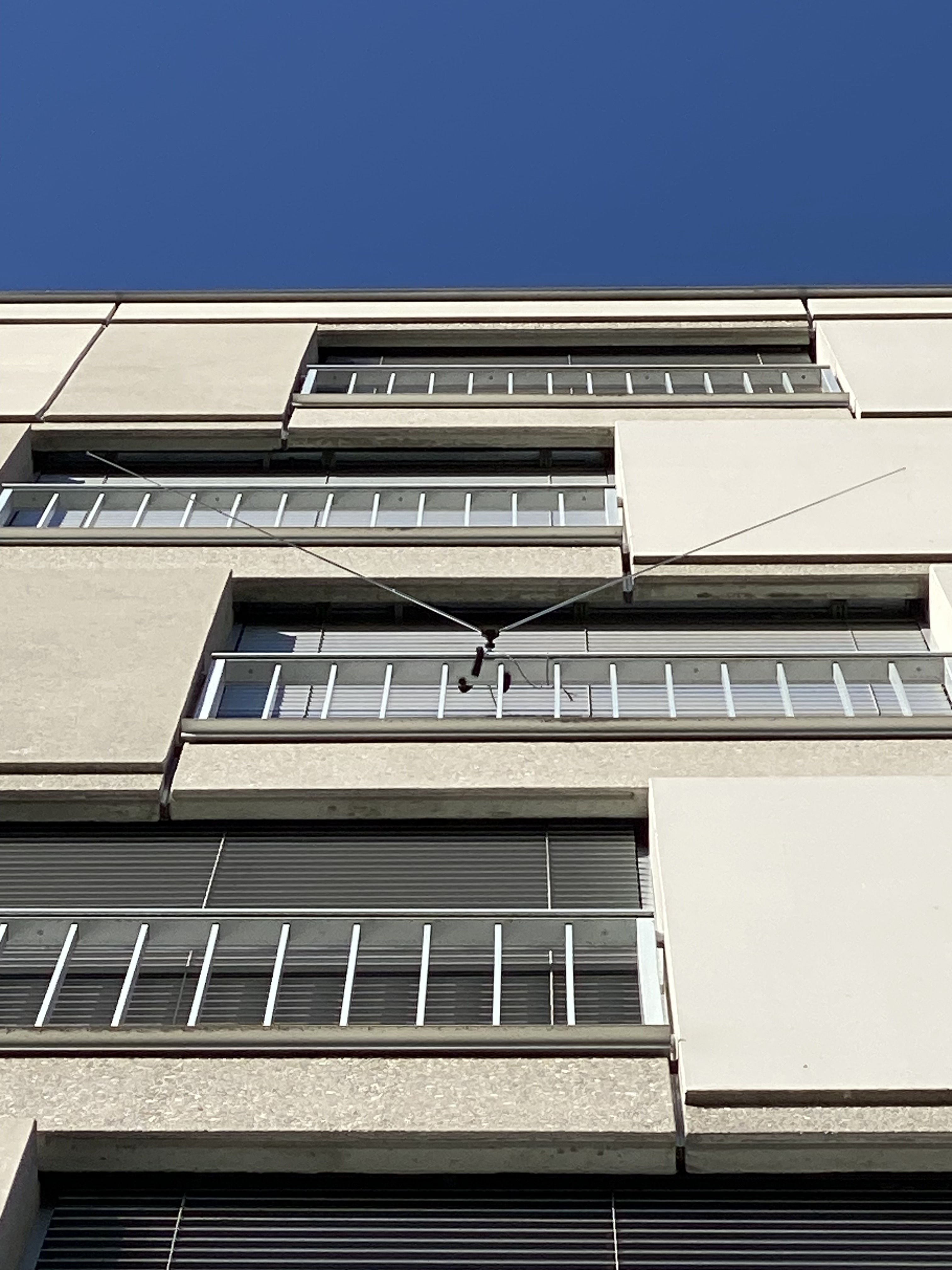
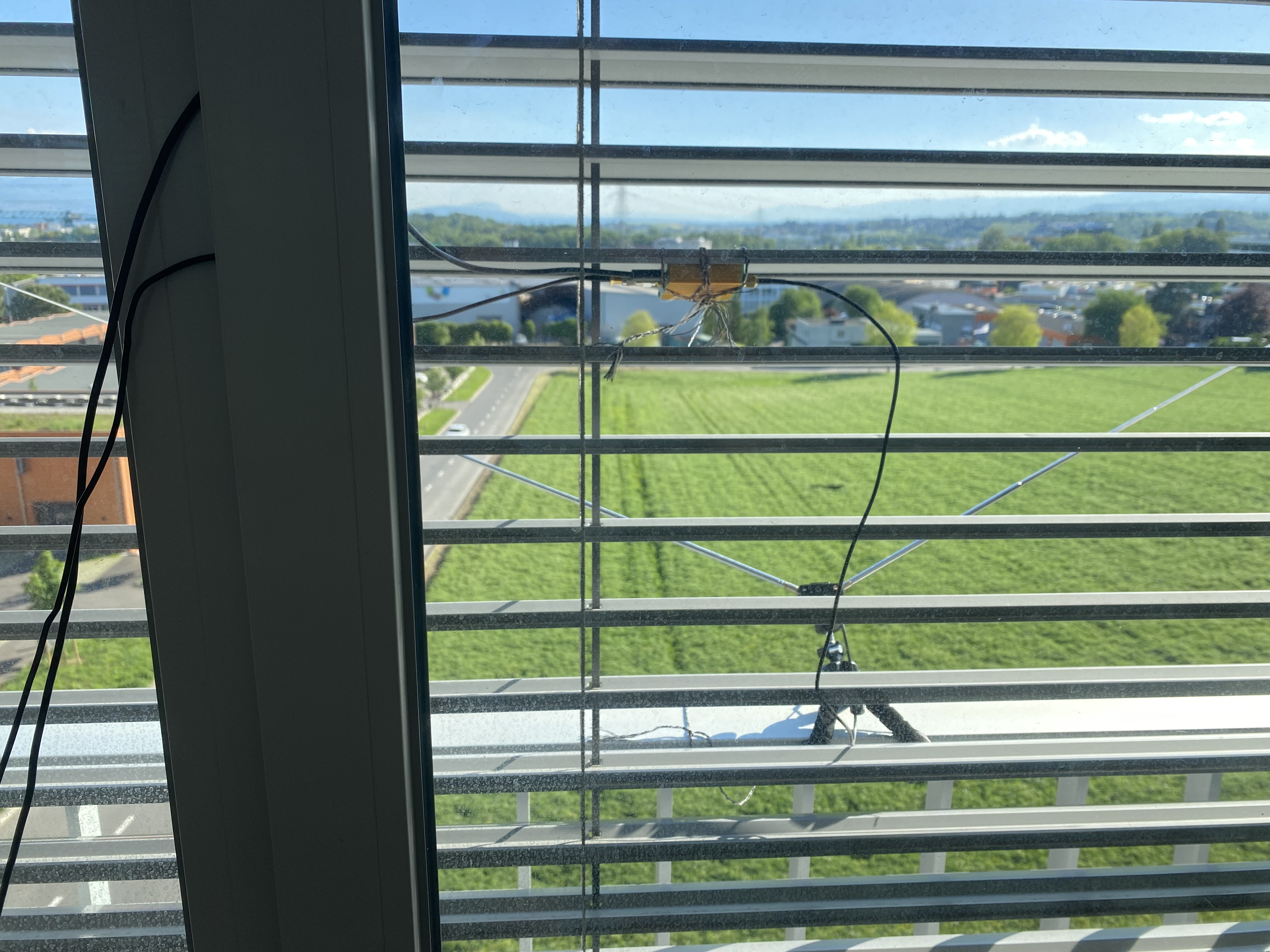
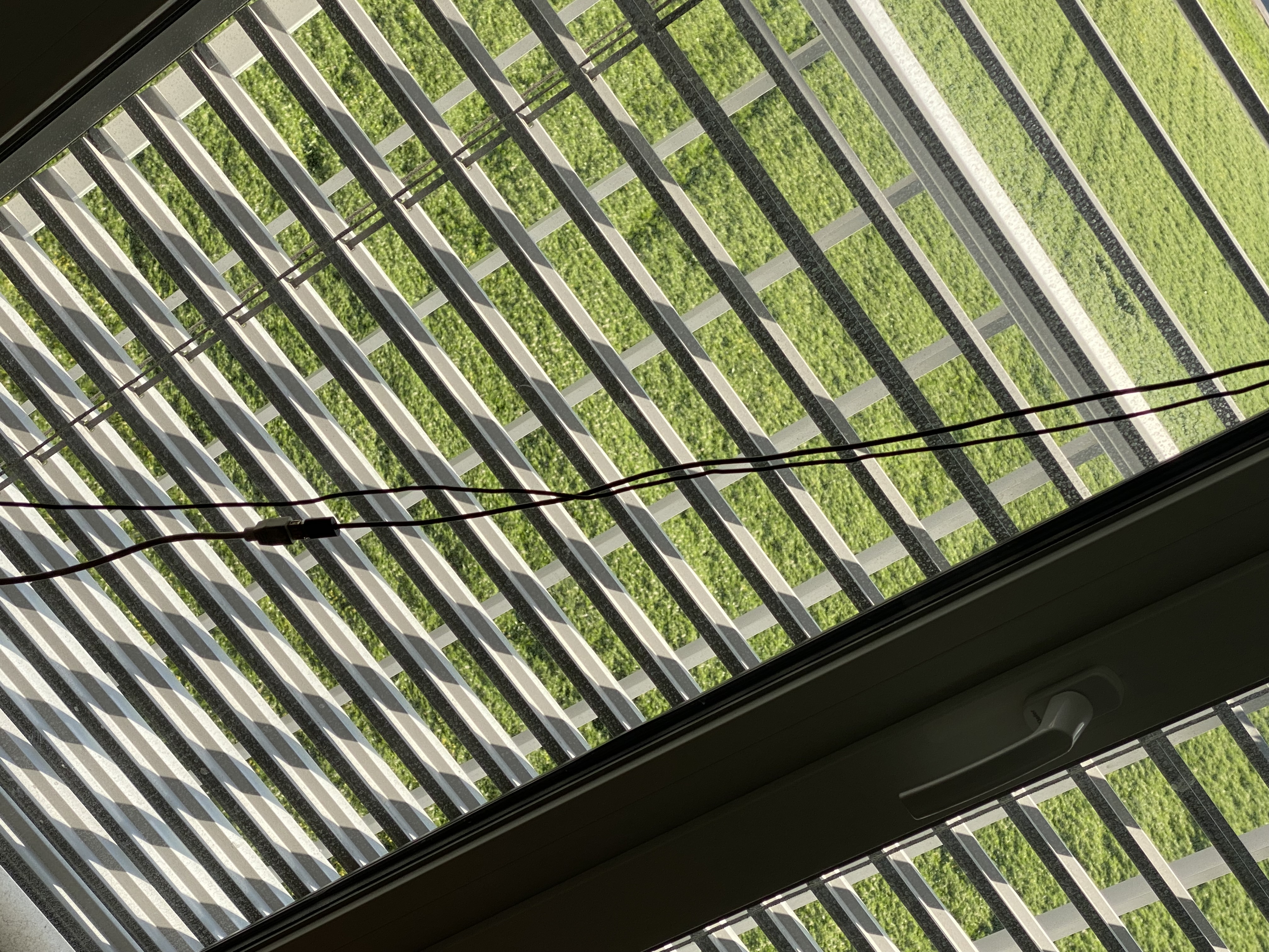
So I got questions about my setup.
I took pictures.
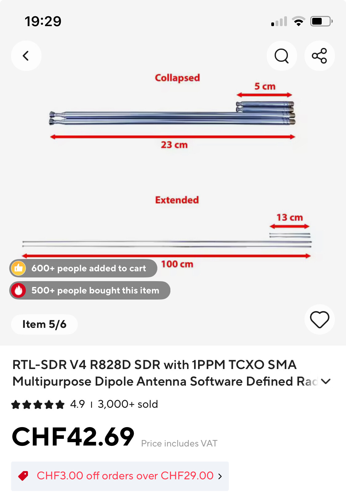
The V angle should be 120deg. Each leg should be 100cm.
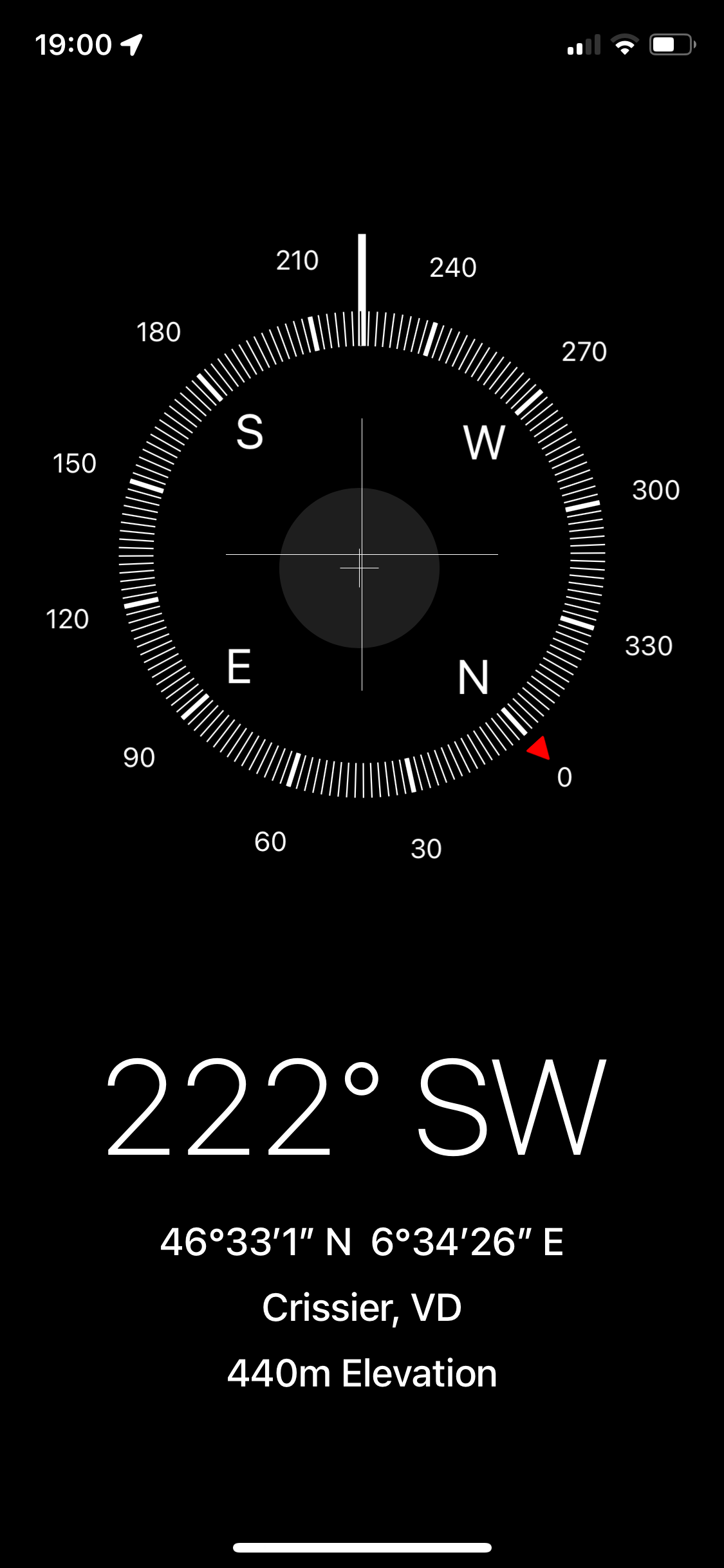
The V is pointing to that direction from my phone compass.
The coaxial cable and the USB 5V of the LNA are going through the window. Yes, the window is closed and the cable are pressed. Maybe this might be a problem?
The power 5V USB cable has a an extension that might bring some instability in power, but the LNA is on battery. Not sure what circuit is inside tough for power.
I agree on the angle of the 2 elements being 120 degrees when using it as V dipole. Your orientation (horizontal, pointing close to south as possible) also looks OK for passes coming from south to north, north to south passes should be bad RX because of the building blocking the signal.
What I don’t get is, why 2 times 100 cm.
Rule of thumb, my old man teached me, go for a quarter wavelength of the frequency you want to receive. So for 436 MHz that would make theoretically 300/frequency and divided by four, but practical closer to 73 / frequency for a quarter wave, being 2 times 16. cm for UHF / 436 MHz
For 140 MHz (as average for 137 to 146 MHz) they should be about 51 cm each. As you notice, on 3 times the frequency the length is also reduced by 3 times.
the 100 cm you are running now matches best for about 70 MHz which is close to FM broadcast band, which is what you don’t want to receive the best, as John also noticed.
For dipoles, the length is frequency. a narrow element has narrow bandwidth as well. you can make them wider in frequency by building the elements as cages (solid not needed), look up “cage dipole”. also possible to make them multi band, on hf it’s usually called “fan dipole” but is pretty simple to do for vhf+uhf as well. gain is also a function of directionality, how much of a sphere you can squeeze into just one direction instead. directionality can often help in not hearing (as well) what is on the back of the antenna.