Hi there!
I am working on a CubeSat project for which I am trying to adapt the SatNOGS-COMMS Board to use on.
I am following the schematics from the gitlab repo here to understand the working of the board, and there were a few things I didn’t quite understand, and I was hoping to get the answers to my queries here on the forum.
1.) In S-band TX path, U604, the attenuator PAT0816-C-10DB, is required to safeguard the RF mixer from high incoming power, as mentioned in the system design document of this project here
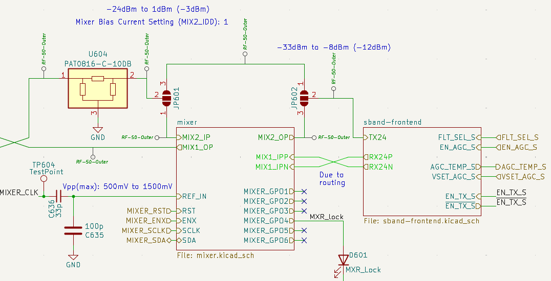
So why should the path bypassing the mixer also include the attenuator? Also, how to take care of impedance matching once soldering is introduced on the RF path?
2.) In S-band TX path, 2 stage amplification has been implemented.
U903, the amplifier SKY66312-11 and U908, the LPF LFCG-2250+ both are unsuitable for the band of operation of SatNOGS-COMMS. Wouldn’t this change the TX frequency to those out of its band of operation? Also, wouldn’t having 2 stage amplification, along with duplicated BPF increase insertion losses?
3.) In S-band RX, can I switch the HPF before LNA to an LPF (similar to S-band RX), to get high frequency noises removed before amplification? Is there some trade-off there I am missing?
4.) In UHF RX, unlike S-band RX, transformers have been used as baluns. Is there some frequency-specific reasoning behind this choice? Is that the similar case for having lumped element filters in UHF TX, unlike S-band RX?
It will be great if someone can help
Thanks. ![]()