Help Needed: Trouble Receiving or Capturing Signals from CubeSats

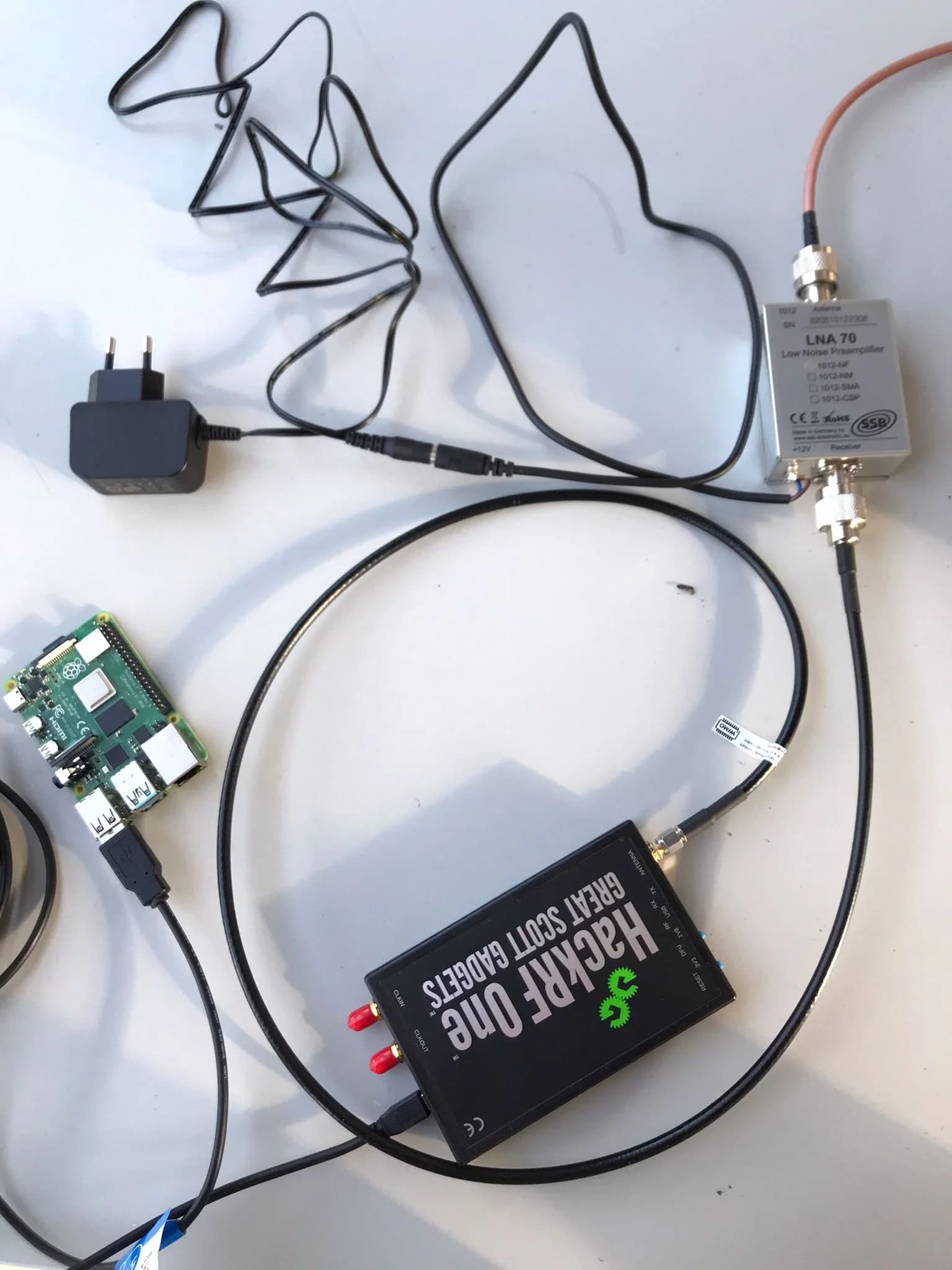
Hi, I am currently attempting to capture and detect signals from CubeSats within the frequency range of 430 to 440 MHz. To accomplish this, I have an automated tracking system consisting of Gpredict and a Yaesu G5500DC, a 30-element 70 cm cross yagi antenna, a coaxial phasing harness cable to achieve RHCP (included with the antenna), as well as a HackRF One, Raspberry Pi 4B, and an LNA with a built-in Bandpass filter. The LNA is powered by a 12V DC wall power supply, as shown in the image below. For signal processing, I am utilizing GNU Radio Companion.
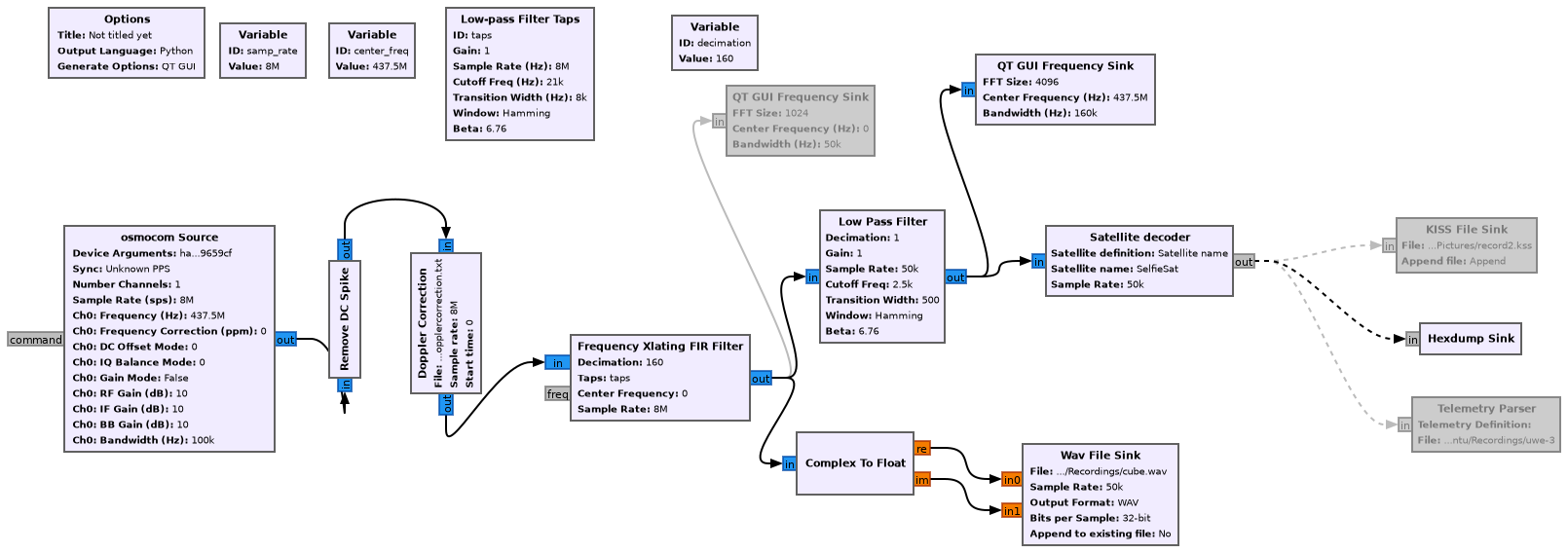
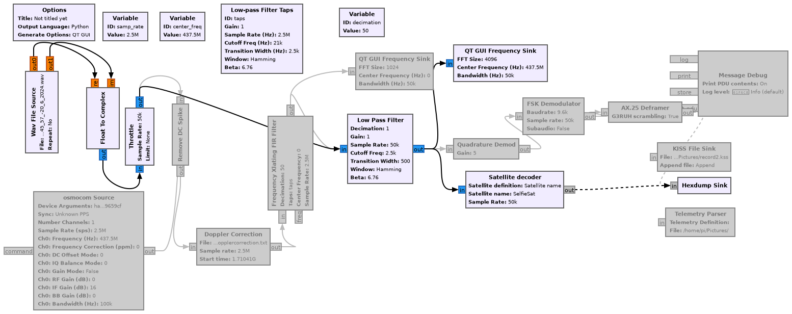
Unfortunately, I havenā€™t detected any signals yet, and I donā€™t know where the problem lies. Could it be that my setup is missing a component? Should I add a power supply or anything else? I created this flowgraph to detect a signal for TIGRISAT.


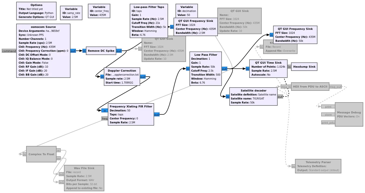
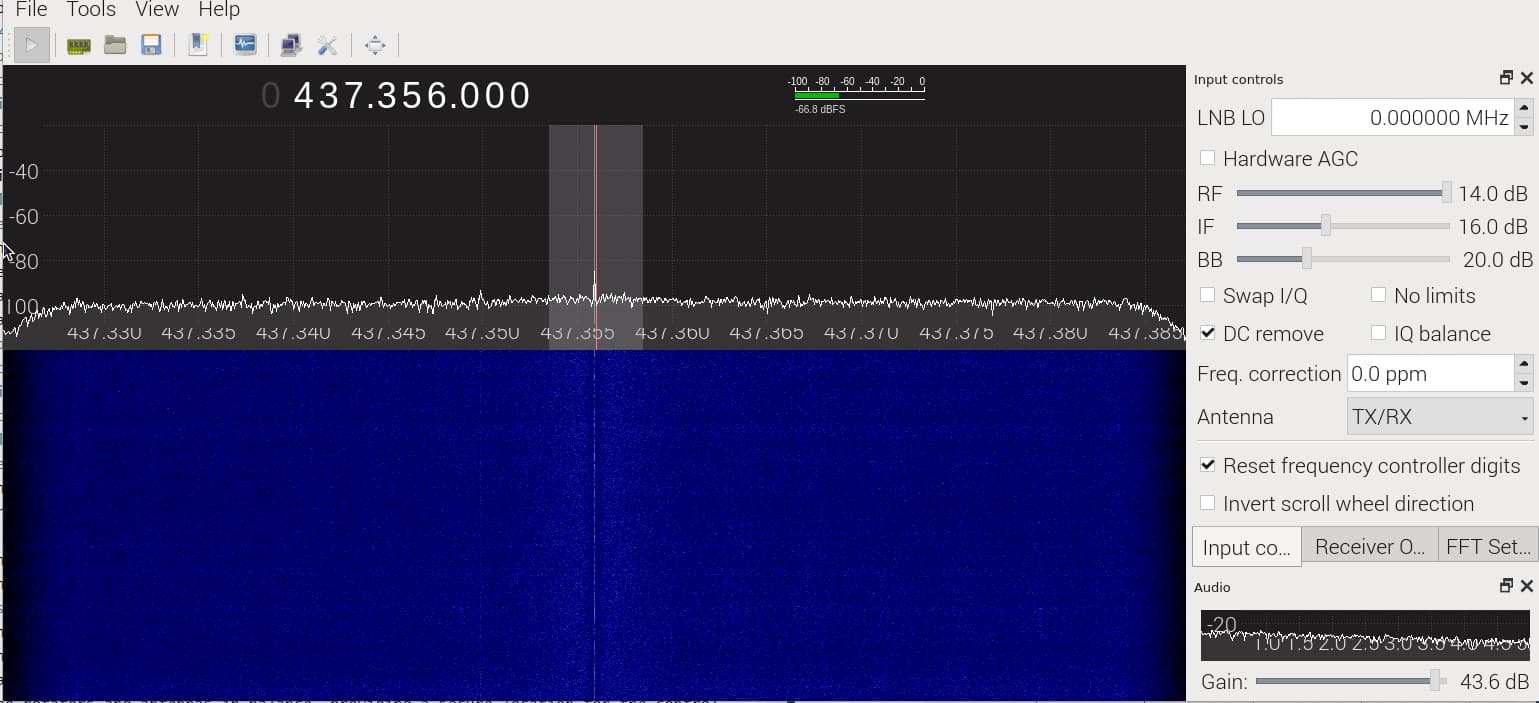
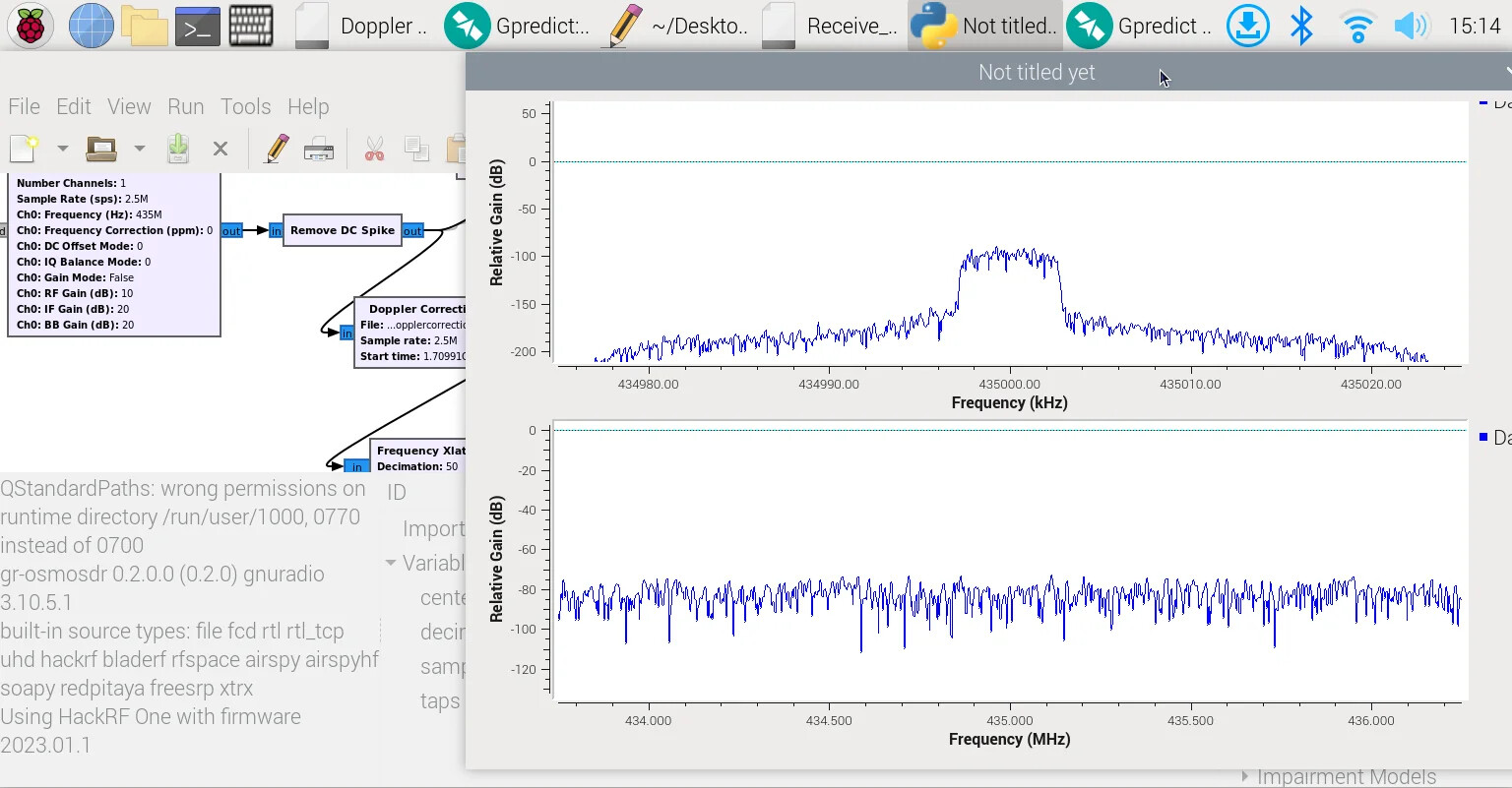
I connected two QT frequency sink blocks: one for the raw signal (graph below) and the second one for the signal (graph above) after the LPF. But neither of them showed any spikes or changes. I even added a time block to see if anything happened, but there was no activity at all.

Information that might help:
On the raspi the only configuration for the HackRF One was to install the driver (sudo apt-get install hackrf) and some dependecies
The LNA is coupled with this wall adapter for the 12 V power supply.
Coaxial phasing harness cable to achieve RHCP
Antenna

Install GQRX or similar and do some manual tuning and look for signals in the Waterfall screen. This will also help you in determining gain settings and show changes when you enable the LNA.

Optimal, the LNA needs to be as close as possible to the antenna.

Maybe it is also possible to just use the antenna without all the extraā€™s to see if is working as expected and then move from there.

GPredict can inform you if there are Satellites passing.

Hi ed190,

I found a reasonably simple way to fault find/test your RPi/SDR hardware setup and to establish the optimum gain & PPM settings was to use the PiSDR image by Luigi Cruz. Luigi has built this for a RPi with heaps of useful ham radio software already installed. PiSDR has a Desktop GUI and you can run GQRX which is a fairly simple SDR program. It does need a display, keyboard and mouse ā€“ just temporarilyā€¦but I gather you have that already.

Here is the linkā€¦.GitHub - luigifcruz/pisdr-image: šŸ„§ A SDR Linux Distro for the Raspberry Pi and other SBC. Compatible out of the box with multiple SDR.. Just download the ā€˜2022-01-07-PiSDR-vanilla.img.xzā€™ iso and burn it to another SD card. Pull out the existing SD card, connect the screen, keyboard & mouse, pop in the PiSDR card and power it up. You will have to configure the usual language, timezone & keyboard stuff but that is quick. Donā€™t bother with updates unless you want this for long term useā€¦there are a lot and it takes a while.

Once you have done that, fire up GQRX as suggested by Jan PE0SAT and just Scan for Devicesā€¦ā€¦Then select the HackRF deviceā€¦I am pretty sure it has the correct Device String automatically set.

For setting gains the SatNOGS Wiki ā€˜Buildā€™ > ā€˜Omnidriectional Station Howtoā€™ > ā€˜Setting the gainā€™ā€¦.shows how to adjust the gain so that the noise floor just starts to riseā€¦.this is generally about the right level. This method uses GQRX instead of ā€˜Soapyremote-serverā€™+Cubic SDR which, in my view is too hard for novices to get going. The link is Omnidirectional Station How To - SatNOGS Wiki

You should be able to listen to terrestrial signals, FM stations and strong satellites like the ISS or AO-73 when they come overā€¦ā€¦all using your existing antennas, LNA, SDR and RPi, etc. That lets you get the hardware all working fine.

When you are happy with the hardware config and have determined the optimum gain & PPM settings then you can put back the original SD card and go from there to debug your software setup.

Just a note on the LNA. You really should have that up at the antenna to be most effectiveā€¦but that means a waterproof housing and a DC feed. If your feeder run is not long leave it out while testing.

Hope this helps.

John ā€“ VK4JBE

Hi ed190,

One more comment about your RF setup. Your 30 element 70cm yagi is only going to have a small aperture. To make sure that pointing it at the satellite correctly is not the issue I would suggest a simpler antenna for testingā€¦an omni or a small turnstileā€¦even a simple dipole.

I use a small 70cm turnstile antenna on my SatNOGS station 1936. I just checked my reception records for TIGRISAT and I get decoded data on just about every pass I capture.

The configuration is a turnstile antenna, Mini-Circuits HPF, RTL-SDR BLOG LNA (all up at the antenna), 20m RG213 Coax, a RTL-SDR into a RPi 3B+. Pretty simple really but reasonably good results on that sat.

The RTL-SDR Blog LNA is 4.5v and can be fed from the RTL-SDRā€™s internal Bias-Teeā€¦.that simplifies things. The HackRF can also do internal Bias-Tee at 4.5v. You may need a seperate Bias-Tee to feed 12v up to your LNA (if it can support Bias-Tee feedā€¦ā€¦most do).

Also make sure you have a decent power supply for your RPi as it is also feeding the HackRF. RPi performance can be very hit & miss/misleading if the PS is not up to it. I use a POE Hat fed from a POE switch and have no problems.

This may eliminate some more issues for you.

Regards,
John - VK4JBE

2 Likes

Hi ed190,

It seems like you are making progressā€¦ā€¦you are getting decoding which suggests it is basically ok. Now for some opimising.

Looking at the waterfall I can see a number of thingsā€¦ā€¦

  1. The noise floor is about -100dBm and the signal at what looks like a strongish instant in the pass is about -90dBmā€¦.ignoring the spiky peaks. That is only a 10dB SNR. Depending on the modulation, encryption and data speed you genenerally need a SNR of 15-20 dB to get good solid decodes allowing for fades etc. So you need to improve the signal without raising the noise floor.

  2. The rest of the waterfall had lots of fades. Any data received in a fade will probably not decode. Circular polarisation tends to minimise fades, so I am not sure why you are getting those. Something else to look at. Do you see those fades in a terresterial signal.

  3. There appear to be no interferers, so that is not an issue.

As for your yagiā€¦ā€¦.Before you start pulling elements of your 30-element crossed yagi can I ask is it actually 15x15 elements. The reason for asking is that a 30x30 element would have a very narrow beamwidth and would be very difficult to point, whereas a 15x15-element cross yagi is probably fine. I would expect 14-16dBi and ~45 degree beamwidthā€¦ā€¦so if that is the case donā€™t pull elements off your yagi.

Assuming it is 15x15-element then some other things need to be checked.

You said the LNA is up at the antenna so that is good. It looks like a SSB LNA 70 with 430-440 BPF, 21dB gain and 0.8dB NF, so that should be fine. It does not appear to be Bias-Tee fed so I am assuming you have a 12v feed up to the LNAā€¦ā€¦hopefully not too much voltage loss in the lineā€¦ā€¦although the LNA spec is 8-14V. Something to check.

On the coaxā€¦.what type of coax is it, how long is it and is it properly waterproofed? You can get away with a reasonably long length of coax if you have the LNA up at the antennaā€¦ā€¦so I assume that is ok, but water in a coax can atttenuate things. You could test it by connecting the HackRF directly to the antenna and check the level and then add the coax and check it down in the shack. I would expect 2-4dB of loss. If you get more that could be an issue.

Given you have a pretty good antenna and LNA up near the antenna and assuming 3dB coax loss I would have assumed a stronger signal from many satelltiesā€¦ā€¦perhaps -70 to -80dBm. On a noise floor of -100dBm that should give you 20-30dB of SNR. The circular polarisation should limit the fades. You are not getting that, so basically something seems to be not right.

I would find a local 70cm signal and start debugging. Eliminate and add things. You know the rough gains. See if the changes make sense.

Hope this helps.

Regards,
John - VK4JBE

Hi ed190,

The other thing that could explain the few decodes is if doppler and antenna tracking are not right. When the sat is directly overhead the signal is strongest and the doppler offset is minimal (although it changes quickly).

I assume you are using Gpredict to control GQRX/GNURadio for doppler correction of the frequency. If the doppler correction is not working then that would cause problems in decoding. I have not done this combo for a while so I canā€™t remember how to set it all up. Just make sure your frequency is changing in line with the satellites movement. Typically slow changes at the start, then fast overhead and finally slow again at the end.

I also assume you are using Gpredict to control the G5500 rotator. Presumably via Hamlib and a interface such as the K3NG or similar. It is a bit hard to tell if you are pointing correctly but if you are the signal should remain strong (sat fades excepted)

The point to recognise on tracking satellites is that we are using a software prediction of where the satellite is located to point the antenna and to correct the doppler offset in the frequency. Predictions rely on a few basic thingsā€¦ā€¦you need your location (lat/long) to be correctā€¦ā€¦you need your computer clock to be correctā€¦ā€¦and you need the TLE/Keplerian elements to be up to date. If these are off then you will probably be pointing the antenna at the wrong place and the receive frequency will be wrongā€¦ā€¦this is made worse with very narrow beamwidth high gain antennas.

Getting your lat/long is pretty easy. The Raspberry Pi should have a NTP time client/server running so it should be OK if it has an internet connection. Get the latest TLE on a regular basis. Make sure all of those things are right.

I note you are using GNURadio to decode things. This can be a bit tricky where doppler for data reception is considered. Can I suggest you have a read of Daniel Estevezā€™s comment on Doppler Tracking in GNURadioā€¦ā€¦Doppler correction with GNURadio ā€“ Daniel EstĆ©vez

The real issue is that you want to aviod step changes in frequency and rather make it a smooth change. The step change upsets the receiver for a small timeā€¦ā€¦not noticable to the ear but an issue for data. He gives a solution so have a look at that.

Hope this helps.

Regards,
John ā€“ VK4JBE

I captured a screenshot of ZACUBE-1 as it passed overhead. The signal appears to be quite weak overall.

I have not heard ZACUBE-1 for many years. To check, choose active satellites. Activity can be viewed here:
https://dashboard.satnogs.org/

Be careful, there are also already re-entered satellites.

Also see:
https://db.satnogs.org/

Yeah I noticed that Gpredict gave me that CubeSat. Even though I set TLE source as https://db.satnogs.org/api/tle/?format=3le.
Here is ZACUBE-1 : SatNOGS DB - ZACUBE-1 it says is operational

As mention by @EU1SAT it hasnā€™t be decoded in a long time, but it is still in orbit.

Maybe this link can give you an idea on what systems are active and can be decoded

1 Like

Hi ed190,

Thanks for the extra info. You have some pretty nice gear there.

I think you are right about the low signal. I think I would start by eliminating as much as possible and go from there. Also it would be good to find a consistent signal that you can test your receive with. If there was a local beacon or repeater that you can listen toā€¦that will eliminate some variables that you get with satellites. Just remember that repeaters are generally vertically polarised and beacons are often horizontalā€¦ā€¦but check. Some satellites are low powered but some strong ones include CIRBE on 437.250MHz that transmitts every 20 sec or so. TECHSAT 1B on 435.225MHz is also pretty good. Have a look on SatNOGS and see which ones are strongest. Have a look a Jan - PE0SATā€™s link for a full list of satellites he is decoding.

Your yagi appears to be an Antennas-Amplifiers 70cm30CROSS (ie 15x15-element). These have a seperate vertical antenna and a seperate horizontal antenna. Each one is 50 ohms and they are seperated by 173mm (a quarter wave length at 70cm) on the boomā€¦ā€¦.so we can connect a 70cm receiver directly to each one and test it. The cable length is basically irrelevant then.

In the photo it looks like the antenna is at ground level so if you can take your HackRF and RPI4 out to the antenna and connect it directly this should give you very good signals. Do the test on both the vertical antenna and the horizontal antenna to make sure they are both ok. If both the signals are still bad then I would be looking at your SDR and the common cables. Try another SDR with different cablesā€¦.perhaps a cheap RTL-SDR Blog V3.

Assuming you get good signalsā€¦ā€¦I would add the LNA next and see if that is working OK. Just by way of comment, I would generally avoid those small wall plugs for powering RF kit. Use something with decent filtering. For testing you could use a 12v batteryā€¦that will be clean. If you connect the HackRF directly to the LNA you may have to reduce the HackRF gain a bit so it is not overloaded. If your signals look OK after that test I would ignore the WIMO polarization switch for the moment and simply move the HackRF & Rpi inside and add the long coax. Remember to optimise your RF gain settings again.

If that looks OK I would do some tests on the satellites using just vertical or horizontal antennas and see how that goes.

The reason for avoiding the Polarization stuff is that to produce circular polarization you need to feed two antennas into a single receiver (so there is an impedance matching issue) plus you need to get the phasing between the antennas correct. This phasing can be done by physically by offsetting the two antenas or using coax phasing or a combination. Here is a good link that explains it all. Satellite Antenna Circular polarization

Your 70cm30CROSS antenna has the elements spaced at 173mm which is a quarter wavelength at 433.5MHz so the polarization difference is sorted by the physical seperation. Just need to keep the two feeder lengths the same. I am not sure how your WIMO Polarization Switcher manages all the impedance transformations for the various setting but I assume it does it internally. This means you should be able to use two equal length coaxā€™s from the WIMO Polarization box to the antennaā€¦ā€¦Which I think you have doneā€¦ā€¦and the output impedance should always be 50 ohms. I gather with no DC power connected to the polarization box it is in horizontal polarization configuration.

You can see why leaving that to last is probably simplestā€¦.If you are happy with the satellite reception then you can add that back and make sure the levels are ok.

You have some good gear and it should work so I hope this all helps you debug it.

Regards,
John ā€“ VK4JBE

1 Like

Hi ed190,

Just a couple of things about your installation that you may care to look at.

I notice from the photo that your antenna is pretty close to the large building. This will obviously block signals for about 180 degrees of your coverage. Being so close it may also cause some odd reflections and hence impact the signal levels and qualityā€¦ā€¦reflections can also act as interferes on data signalsā€¦.ie self interference.

I note the antenna manufacture recommends a fiberglass boom. It is a bit hard to tell from the picture but your boom looks like metal. That could also impact things.

The WIMO Polarization Switcher is mounted with the connectors coming out sideways. Many years of radio experience shows that this is a good way to let water get into your connectors and into the boxā€¦ā€¦. The better way to mount it is so that the connectors point down and the cables come up from below. This way water runs away from the connectors and box entry point. The loop in the cable (if it comes from above) acts as a drip point.

I would also use some good coax sealing tape when you have it all working. As a temporary measure you could use electrical tape but note that will degrade over time and leak.

Hope this helps.

John - VK4JBE

1 Like

Hi ed190,

I just noticed in your more recent dumps of the few PDUā€™s that you are getting that there are lots of ā€˜OOOOā€™s which are overflowsā€¦ā€¦. You really need to get that under control as it will probably be another factor affecting data decodes.

You have a few optionsā€¦ā€¦1) play with the sampling rate, decimation/interpolation, FFT sizes, etc in your SDR software, 2) reduce the processor load on your RPi (Ie donā€™t run a GUI) or 3) get a more get a more powerful PC. Start with the sampling rate.

I normally work out a sample rate and decimation using GQRX started with a terminal in the background before I start playing with GNURadioā€¦ā€¦. I must confess it is pretty difficult on a RPi and whilst I can get them low, the overflows never really seem to go away. Others may have better suggestions.

I generally use an ordinary laptop or a VM if I am using GNURadio.

Out of interest SatNOGS is a case of running the GNURadio framework on a RPi without a GUI and it seems to do a pretty good job.

I believe the HackRF SDR has a minimum sample rate of 2Msps. Have a play around and see if you can get it to workā€¦ā€¦or at lease minimise the overflows.

I will be interested to see how you get on.

John - VK4JBE

Hi vk4jbe,

So, I started off with a sample rate of 8 Mbps and a decimation value of 128 since GQRX set it up as the default and didnā€™t give me the option to go lower. But when I tried the same settings in GNU Radio, I ended up with a bunch of "0"s. So, I dialed down the sample rate to 2.5 Mbps and set the decimation to 50. Still saw some "0"s, but definitely less than before. Next week, Iā€™ll tweak these settings further and give it another shot with a recorded cubesat signal in vertical polarization to check its strength. Oh, and by the way, Iā€™ve got to swap out one of the cables connected to the LNA; it got damaged somehow. And yeah, Iā€™ll also try shrinking the FFT size since it seems to be bogging things down.

I am using a Raspi due to its portability. I use my laptop to interface with it via RealVNC. The HackRF is also located outside, protected from the weather. I do this because itā€™s cold outside, and I can check the antenna from indoors. The setup includes a VHF (144-146 MHz) antenna adjacent to the UHF antenna. I will see if I can receive a signal on the VHF. The purpose of the antenna later is for transmitting signals.

Regards

Hi ed190,

Good to see you making progress.

I am a bit intrigued by your setup. You mentioned that the HackRF and RPi are out near the antenna. Where is the G5500DC Rotator Controller and the K3NG Arduino? I am assuming from what you say they must be out near the antenna also. I can only assume you have a small room with AC power, LAN, etc out near the antennaā€¦ā€¦.or a very big waterproof box!!!

If you are running Gpredict for the antenna az/el, GNURadio for receiving/decoding, the GUI and RealVNC all on a RPi I think you will be pushing its limits a bit. You might be better off with a NUC if you have a small room.

Alternatively, if you can run the Gpredict and GNURadio on your laptop, you might try some of the USB-over-IP tools to extend the USB out to the RPiā€¦ā€¦ Native linux has ā€˜usbipā€™ and there are other tools like VirtualHere, etc. I have not tried these but they might allow you to shift the heavy processing load off the RPi to your more powerful laptop and let the RPi just handle the USB transportā€¦ā€¦with a headless linux install.

Just a thought.

John - VK4JBE

Hi John,

Sorry for the super late response, Iā€™ve had a lot going on lately.

I made modifications to the setup. I placed the LNA closer to the antenna and bought a DCC 5000 Pro, which is a T-bias to provide 12V DC to the LNA.

For Gpredict and GNU Radio, I left the Raspberry Pi to control Gpredict to minimize the process load and installed the Windows Subsystem for Linux with Ubuntu on my laptop to run GNU Radio. However, I didnā€™t see many changes. The only noticeable difference was that when running GNU Radio with the HackRF One, the ā€œoā€ was never printed in the terminal, so there are no more overflows.

I conducted the following experiment: I set everything up to capture signals from UWE-3, SALSAT, and SelfieSat. I configured the flowgraph to store the signal so I could process the same signal later and compare the results. Hereā€™s how it went:

I got only PDUs from SelfieSat while tracking it in real-time (flowgraph is below). These were:

VERBOSE PDU DEBUG PRINT
((transmitter . 9k6 FSK downlink))
pdu length = 49 bytes
pdu vector contents =
0000: bc 47 87 a5 91 d8 91 ec 75 bd f7 a5 37 b8 5e 04
0010: 3a 0c 0f a6 bf 4c d1 e2 c9 84 1b 73 63 92 4f ea
0020: 5e 68 a4 a4 cf 7d e2 71 45 53 79 d6 ac 22 1f 6b
0030: 83

The signal was saved as a WAV file, and I tried to play the signals three times again (see the flowgraph below) to see if the same PDUs were printed.

Try 1: VERBOSE PDU DEBUG PRINT
((transmitter . 9k6 FSK downlink))
pdu length = 12 bytes
pdu vector contents =
0000: c0 a5 61 15 16 de fa e9 1d 82 ca 9d


Try 2: VERBOSE PDU DEBUG PRINT
((transmitter . 9k6 FSK downlink))
pdu length = 4 bytes
pdu vector contents =
0000: 34 87 6a 1b


Try 3: VERBOSE PDU DEBUG PRINT
((transmitter . 9k6 FSK downlink))
pdu length = 10 bytes
pdu vector contents =
0000: c0 13 c1 01 4e a0 ca 10 98 06


VERBOSE PDU DEBUG PRINT
((transmitter . 9k6 FSK downlink))
pdu length = 22 bytes
pdu vector contents =
0000: b0 cd af a3 e2 ce f4 7a 8f 45 0d b7 6b 5e 29 64
0010: 14 a1 77 ad dc 79


I canā€™t understand why the signal delivers different results after being played three different times.

Hi ed190,

No problems on the delayā€¦ā€¦

It looks like your current RPi/PC config has gotten rid of the overflow problem and the LNA situation sounds a much better.

I had a look at the format for the data that SelfieSat-1 sends. Orbit NTNU, who built the satellite, says the data format is 9600 2-FSK AX.25 G3RUH. SatNOGS has the same. The SatYaml file used by your GNURadio flowgraph should reflect this in the ā€˜transmittersā€™ section. I have not looked at that yet but it would be worth checking that your SatYaml file agrees with that.

The next thing I checked, and this confuses me a bit, was what some of the SatNOGS data from recent passes looks like. They all seem to be a constant length frame that starts with the sequence 05 00 85 01 etcā€¦. But they are not decoded as AX25ā€¦.that is odd. Perhaps it is just hex not AX25.

Comparing those to your frames which are variable in length and donā€™t start with the usual sequence. It sounds like it is not decoding correctly.

I had a quick look at your GNURadio flow graphsā€¦ā€¦The LPF Taps in the Frequency Xlating FIR Filter has a cutoff of 21kHz and the LPF that you have after it is 2.5kHz. 2.5kHz is too narrow for 9600. I would widen the 2nd LPF up to 10kHzā€¦ā€¦I am not 100% sure you even need it. You could try just bypassing it. I note you have Frequency Sink before and after the LPF. See what they indicate to optimise the filterā€¦.if it is needed.

If you wanted to test your decoder out you could download the .ogg files from some of the stations that have successfully decoded data from SelfieSat and play them back through your decoder to see if they work.

Those are my thoughts for now. Others may care to comment.

Regards,
John - VK4JBE

Hi John - VK4JBE,

Thanks for your feedback. I will try to implement other blocks in the flowgraph to see if there is a change in the demodulation and decoding, instead of using the satellite decoder contained in gr-satellites. I changed the cutoff frequency to 10k, but it didnā€™t do much. I got other types of PDUs. I didnā€™t quite understand why the cutoff frequency has anything to do with the baud rate.

This week, I will try, with the help of others, to receive a signal in horizontal polarization to see if the antenna setup or the flowgraph is affecting optimal reception.

Regards,

ed190

Hi ed190,

Given your comment that you donā€™t understand why the cutoff frequency has anything to do with the baud rate, I suggest you probably need to learn some of the basics of digital signal processing. It will help debugging GNURadio flowgraphs. The attached video from Rohde & Schwarz is a fairly simple explanation of how FSK works including the bandwidth. Have a look at it. It will give you some clues as to how it works. https://www.youtube.com/watch?v=ogJB5fiQ9kM

I donā€™t fully understand the SelfieSat FSK modulation parameters and so I may have misled you on the bandwidth of the signal. That filter may need to be 20kHz+ā€¦.ie the same as the Freq Xlating FIR Filter.

I still suggest you download a good SelfieSat pass audio file from SatNOGS (one with decoded data) and play that through your gr-satellites decoder. That is what SatNOGS uses so it must work. It has to be something you are doing with the other blocks around it.

Good Luck,
John - VK4JBE