Hi! I don’t know if the category is good and I wasn’t even sure if I should publish this thread but maybe someone could find it helpful
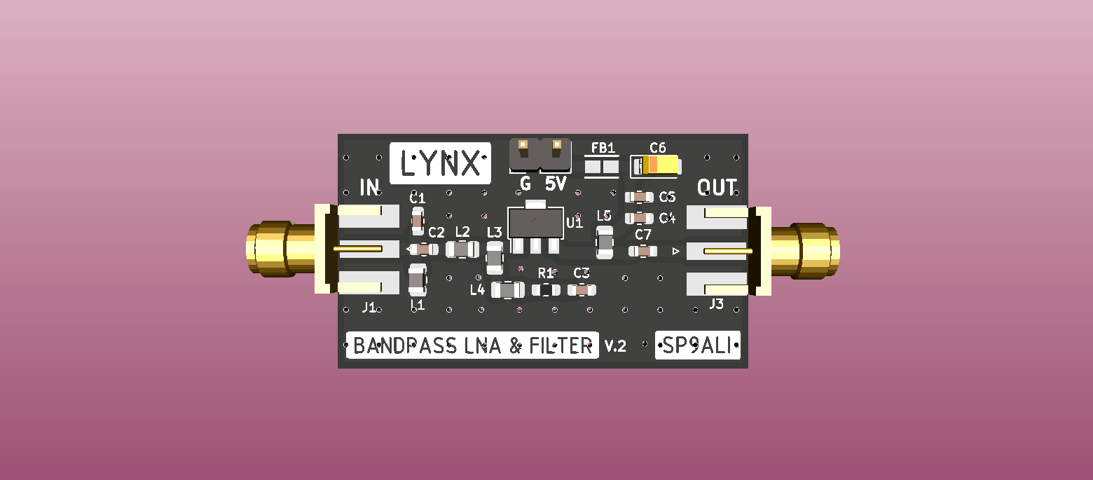
I wrote a step by step tutorial about designing a simple LNA with a bandpass filter for 400-440 MHz from a beginner’s perspective - maybe there are some other beginners in radioelectronics here for whom it might be interesting. When I started this project, I couldn’t find any information about how to start designing this kind of thing - there are some photos of PCBs in the internet but no one shared their experience about how to make it from scratch (or at least I didn’t find anything - if you know any good source, you’re welcome to share it, I’m interested!).
This LNA+filter is now connected to my test ground station (SatNOGS Network - Observations). As I wrote in the article, the observations are better than without it (and better than with cheap one bought on eBay ).
If you have any comments, feel free to share it - remember only that I’m a total beginner and not a professional, so please, try to not be too harsh . Have a nice day!
@sp7thr - no, I don’t have any spare parts, sorry Gave them all to friends.
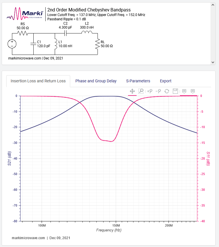
@michal.drzal On my newbie intuitiion it looks quite good, I’d give it a try. You can always try to change edge frequency values a bit (1 MHz up or down) and see if it makes the pink line go lower. But it doesn’t look wrong - switching elements values’ in my design should do the job.
Sorry for the late answer - I didn’t get any notification about these posts
I know it can be annoying when people want more from a project that is already great, so sorry for asking: have you thought about what would be needed to add bias-tee support, so we wouldn’t need separate power supply?
I’m pretty sure that a redesign would be needed to add bias-tee, so I didn’t consider it (as it was my first filter). But if you know electronics, don’t hesitate to take my design and adjust it to your needs, it’s on open license

 ).
).