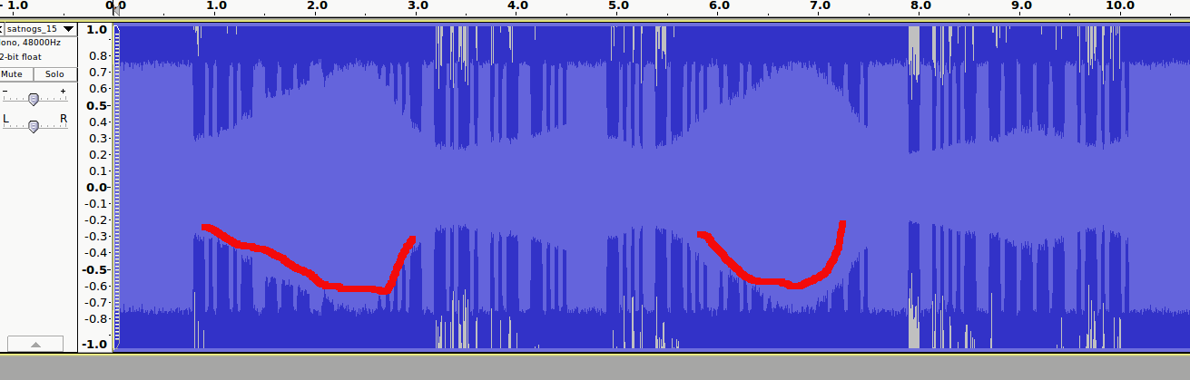
I’m pretty new to gnu radio and cannot understand why signal dropped periodically. See red marks on the screenshot. I’ve noticed same slopes on several observations. Any thoughts? Could it be due to gpredict slow reaction?
Sounds like that recording was made using FM so I’m not sure it should be used for debugging a CW decoder. CW should be recorded using USB mode
Anyway, when the signal drops in strength, maybe due to fading, the noise level from the FM demodulator will increase and that is what you see. You can even hear the background noise increase if you listen to it.
I mean that the audio sounds like noise coming from a frequency demodulator.
CW means continuous wave, which is a single carrier frequency being keyed on and off. You should hear a single tone like in this sample: www.kb9ukd.com/digital/cw20.wav
What you hear instead is changes in the noise profile. Surely you can decode it because you can detect the differences between on and off, but it is not the right way to do it. It was recorded using the wrong receiver.
I suppose you could remodulate it using FM, then demodulate it using SSB receiver, theoretically… It might be easier to make a new recording using the correct receiver, if such a receiver is available in gr-satnogs. I do not know why it is receiving using FM.
This satellite could send signals in CW AM modulated and FSK modulated. Strangely I cannot reliably decode digital signals Maybe due to Lossy .ogg encoding
what @csete said is right, currently we demod everything as FM which makes CW a bit difficult to decode (as well as BPSK and other modes).
Once we have a good cw demod script what will happen is that the client will pick its demod mode given the mode selected for the observation in the network. For now its all FM… Soon we’ll have CW proper.
I can give you some ways to start decoding, are you primarily in linux or windows?
I’m on Mac OS with Ubuntu 14.04 in VirtualBox. According to network.satnogs.org most of the telemetry was sent using CW. So I was wondering if I could decode them altogether.
Cool. @csete offered to work up a cw script and I’ll test this weekend… With proper demod the decoders should work. However, even with our very frequent frequency correction for dopplar shift there is still a lot of jitter in the signal that throws a lot of decoders off.
I am not 100% sure which satellite your trying to decode, but from past experience I have found that most of the signals are circular polarised i.e. Right Hand Circularly Polarised or Left Hand Circularly Polarised, if your using just a simple yagi, i.e. horizontal or vertical your going to find a drop in the signals as the polarity goes out of skew. Even if the satellite is using a dipole antenna, monopole etc if the satellite is spinning (which nearly every one is) then the signal will still be coming back circularly polarised depending on which direction the satellite is spinning in during its orbit. Using a single yagi for reception means the signal will go UP in signal strength and then drop down to almost zero, before gaining in strength and repeating like this. But looking at the received signal it sure looks like this is what is happening.
The signal coming from a linearly polarized TX antenna will stay linear even if the satellite is spinning. A spin will cause a time dependent skew compared to horizontal and vertical, which don’t make sense anyway since the satellite is moving.
Anyway, the best is always to use a circularly polarized antenna to receive satellites even when they TX with linearly polarized antennas. You will only loose 3 dB because of polarization.
I agree that a circularly polarised antenna’s are best and for that reason I use crossed yagi’s and can switch between V, H, RHCP and LHCP polarity but if you have for example a single vertical yagi antenna and the satellite is spinning (as most are to make them more stable whilst in orbit) due to your location on Earth in relation to the satellites antenna, it appears to be sending circularly polarised signals. As you state a 3dB loss in signal from a monopole antenna (at any angle) is at most when received with a circularly polarised antenna, however should you have the wrong polarity the attenuation (loss of signal) is far greater, very many dB (up to 30dB) for example if you try and receive the V monopole with a horizontally polarised yagi.
But think about it like this, imagine a satellite at AOS (acquisition of signal) just as it comes over the horizon, lets say the satellite is just spinning like a spinning top, the mono pole is on the top of the satellite as you look at it is going around but looks stationary to us the observers (giving V polarity), now as the satellite is directly over head the satellite apparent position to us has altered and as we look at it, although the satellite is still spinning, to our position it now appears to sending in H polarity, and at LOS (loss of signal) the satellite has now gone back to V polarity.
A simple way to show this is as follows: Take a pencil in your outstretched arm to your side, the pencil pointing up, V, move your arm in an arch above your head (don’t rotate the pencil or your wrist) as you look up with your head its now H, and move it to the other side of your body (again don’t alter the position of the pencil or your wrist) and as you look is now back to V (except now the pencil should now be upside down).
I have seen those nice illustrations of rotating arrows and what not, and while they are pretty cool, they don’t give a full understanding of circular polarization. Keep in mind that these are electromagnetic waves travelling at the speed of light, so some math is needed to get the full picture.
Circular polarization is defined as two plane waves of equal frequency and amplitude, perpendicular to each other and 90° out of phase. When you look at the resulting E-field vector from a certain angle it will indeed appear to be rotating.
But what is the angular velocity of this rotation? If you look at one of those fancy illustration, you can see that the E-field vector makes one full rotation as the wave travels one full wavelength (at the speed of light). The rotation period is therefore equal to the period of the wave, i.e. T = 1 / frequency
So, for a 145 MHz radio wave to be circularly polarized the E-field vector has to rotate 145 million times per second! — and more as the frequency increases.
I don’t think satellites are spinning that fast
Thus, the signal coming from a spinning satellite using linear polarized antenna is still linear, it just has a skew that changes with the satellite attitude.
Most of the LEO satellites have more than one transmit antenna, even for the same band, as 2 antenna’s cannot be physically in the same place at the same time, so they are not and so quite often one is V polarised and one is H polarised (or even +45 and another -45), they are fed through a matching network and as both are usually deployed and active (unless one fails to deploy after the launch of the satellite) the transmitted signal cannot be just V or H polarised, and therefore is something other, which is regardless of the spin of the satellite.
The spinning of the satellite is used to stabilise its flight, most LEO of any size actually use circularly polarised antennas to help reduce the RX signal against fading, for example. NOAA weather satellites. As most of the LEO’s satellites rarely go overhead and usually are low level passes the amount of skew is even more excessive to the observer on Earth.
However you wish to view the satellites the best solution is and always has been through either a fixed circular polarity antenna (you hope you got the correct polarity or your in trouble) or crossed yagi antennas with which you can select either RHCP, LHCP, V or H polarity. So you could simply switch through the polarity’s at will until you find the perfect match, with almost no fading on the received signal.
But back to my original statement, unless we know what satellite was in question and what antenna was being used for reception, we wont know if the signal was linear, circular or something in between, so we still need to know the satellite and the received antenna set up.