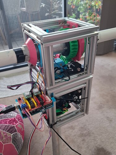
Hi all,
I’ve built the mechanicals for the Satnogs 3.1 rotator, its all ready to go, thought the software would be the easy part. I’ve done some programming in the past, also a little Arduino but not and Arduino Makefile scenario. I’ve been through the forums, YouTube and the like and have been through the readme file linked below, I get to the ‘make’ command and I get lost, can I do this from the Arduino IDE 2.3.2 or do I have to download and install a makefile plugin/script that will run from Windows 10 command line, that will let me run the Makefile for the stepper motor controller. I’ve got Gpredict on the Pi and its ready to run, I have modified the .h files so that 485 will talk as the protocol etc, now its just a matter of getting the Uno R3, CNC shield and drivers to play ball. The older I get its sometimes hard to get my head around these processes, thanks
Not sure if it’s a bigger step to take, but I mostly try to use PlatformIO these days.
I did some work on the firmware to build on it.
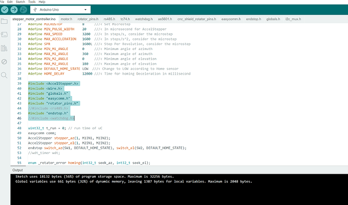
Thanks, I really tried hard the way it was described in the article in the link you sent but just beyond me, couldn’t get my head around it. After a lot of research what I did come up with was this, I found that it seemed like the folder structure of the files wasn’t liked by the IDE, so I put the *.h files in the same folder as the “stepper_motor_controller.ino” file and changed the includes as below, inverted commas instead of the <> symbols and the whole thing DID compile and I loaded it onto the Uno R3.
#include <AccelStepper.h>
#include <Wire.h>
#include “globals.h”
#include “easycomm.h”
#include “rotator_pins.h”
//#include <rs485.h>
#include “endstop.h”
//#include <watchdog.h>
I guess the question is will this approach work, there are no *.cpp or *.c files which sometimes come with *.h files in libraries, just the included header files as per above. Will my approach function or do I need to go back to trying to sort Makefile ?
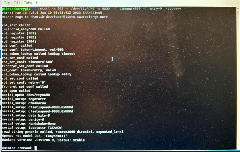
I have now connected my Uno to the pi 3b+ and used the following command but have now removed the -C options to simplify and get the following text from rotctl
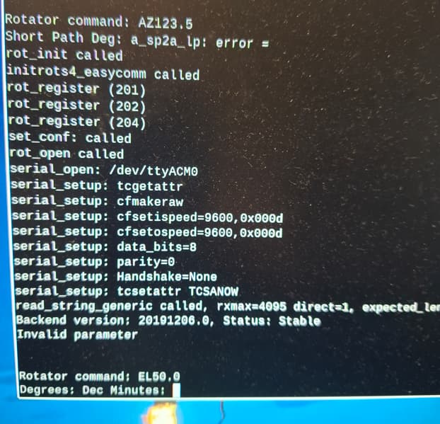
Seems like it is ok and I get a prompt asking “Rotator Command:” I’ve tried AZ123.5, also AZ123, and get an error, have also tried EL50.0 and EL050.0 and get an error BUT ALSO the “Degrees: Dec Minutes:” prompt which by the instructions and easycomm docs shouldnt be happenning as default is Degrees.
I guess the question is, is the .ino file I compiled causing this because I’ve complied it wrong or is now a comms error between pi and UNO, Im so thankful for anyones help, thanks
If you indeed have everything built and running (nicely done), you need to understand that the commands (language) the rotator speaks is one totally different than the rotctl speaks.
get position is p in hamlib, it is translated to easycomm when you specify that as a model -m 202 and is therefore translated to AZ EL to the hardware.
Hamlib is abstracting all the different rotor languages to one, so you should never feed hamlib yaesu or whatever rotator specific commands.
if you type ? you will get a command reference, including:
Commands (some may not be available for this rotator):
P: set_pos     (Azimuth, Elevation)
p: get_pos     ()
For example P 180 45 will set the position, it is translated to AZ180 EL45 in easycomm but that is handled under the hood so to say.
Ahhh, now it makes sense, I disappeared down a rabbit hole and somehow missed/misunderstood the commands. It now looks like I was trying to feed the Easycomm commands straight into a Hamlib function where I should have been giving commands at a higher level (Hamlib level). I have just quickly tried it, commands ‘P 150 45’ and getting a lot better responses from the Uno but haven’t tested the lot yet, Im away from project for a couple days so further testing in a could days time.
The project was started a couple years, had to learn 3d printing as well as a lot of other skills and as finances allowed I built it, really really enjoyed the build. The crossed yagis are built for it as well, just a matter now of finishing the software and testing, once functioning Ill then add wifi to the project to remove the USB cable but thats down the track.
Thankyou so much for your help so far, once back at the project and I can test Ill let you know, I still expect some teething problems though, but that’s projects and the fun of it all isn’t it.
Thankyou ![]()
Thanks for the information, Ive done some more work on it and have a couple more questions, in the documentation I couldn’t find anywhere that talked about the endstop microswitches whether they are NO or NC but I found a photo in the wiki that showed them wired up to the NC contacts of the microswitches so I have changed my from NO to NC. (I’m using as reference all the 3.1 version where I can). Should they be NC, I’ve checked also all the connections on the CNC shield and they appear correct including jumpers on M0 and M1.
When I power everything up the the servo motors start I imagine by the docs looking for the endstops to locate themselves, 2nd question is what happens when they reach the endstops, mine keep on going and then a little later both stepper motors stop, around 90 degrees from the stops, I cant find docs on what happens once the micros are activated, should they (the servos) go for 90 degrees, should they go a full 180 degrees, just need a little guidance.
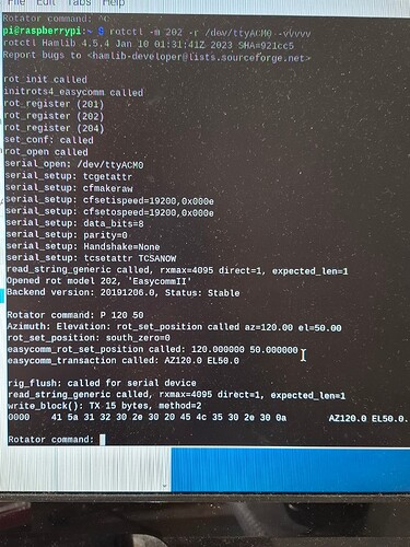
From the screen shot below once it stopped I thought id try a command and used P 120 50, also tried others but nothing happens, I’m using a pi 3b+ and using the serial option (232) as from what I have researched the pi should be able to adjust for 232 or 485, maybe I need to go back to 485 or maybe a compilation problem where this blog originally started. Any guidance appreciated.
The rotator in the below pic is just temporary mounted and wired for testing purposes at present, thanks so much
Configurable
#define DEFAULT_HOME_STATE HIGH ///< Change to LOW according to Home sensor
Configurable
#define MICROSTEP 8 ///< Set Microstep
unfortunately you cannot change this without recalculating
#define MAX_SPEED          3200  ///< In steps/s, consider the microstep
#define MAX_ACCELERATION   1600  ///< In steps/s^2, consider the microstep
#define SPR                1600L ///< Step Per Revolution, consider the microstep
yes, on reset it does homing. if you’re using a regular arduino, it is also reset when you open the com port so expect homing when connecting as well. depending on hw design, this can be disabled in a few ways.
it should try to run for MAX_M1_ANGLE or MAX_M2_ANGLE but will stop after one of them (usually altitude) has run the full span and not found the endstop within that range.
I would recommend having access to the switches and nothing hooked up to the rotating parts so they can freely spin during initial testing. manually operating the microswitches should make respecitve axis stop.
the controller will not respond to positioning command if the homing fails and it goes to error handler.
Ive gone through some more documentation on the CNC shield and have now changed the end stop switches back to NO and the code to STATE HIGH, shall see how that goes,.
Ive also been going through the code as my setup seems to be a hybrid between Quarterpounder’s setup and Agis’s, I’ve left rotator_pins alone as it should suit the setup I have. The easycomm.h though I have live tried various combinations with the code but not sure what is correct and none worked correctly, I’ve compared the two code examples above (Quarterpounder and Agis), I know in the docs QP talked about where in a couple places there were commented out references to the rs485 protocol … The next code edit will remove both the RS485 and watchdog elements from the easycomm.h code. This will allow the PC to talk directly to the Arduino and as such bypass the RPi. The edited code is below, note again the use of comments (//) to remove the lines . However there looks like other code additions, under easycomm_init() function there is now a Serial.begin(9600) and all through the easycomm.h code there is Serial.available and Serial.read and many Serial.print code changes and im wondering if I should be changing these back to rs485.available… etc or just use Agis’s code with the different rotator_pins.h file for the CNC board.
Also in stepper_motor_controller.ino I didn’t find any docs, on changes to the .ino file but I have found at least 5 places that the QP code is different where there are commented out WDT or rs485 lines of code, I’m thinking I need to uncomment these, well I’ve actually tried it and still no proper operation.
What I am thinking is now, make sure I get those end stops correct and that line of code relating to them is set HIGH with N/O switches, now that I understand the code better use the code from Agis which is Pi based and rs485 based, change the rotator_pins.h to the newer version for the shield and give it a crack from there, basically go backwards and start from the beginning again, what are your thoughts, thanks so much for your advice. Thanking you.
IIRC the rs485 stuff does not conflict when used as regular usb-serial or whatever you choose. The main difference is one pin that sets the rs485 half duplex direction, which just does nothing in a rs232 scenario.
You need to get it to do homing first before it wants to respond to position commands, there’s a few more that will respond either way (just not while homing). VE shows version, GS is status and GE is errors. you can find them in the easycomm parsing section.
Disabling WDT basically changes nothing if you’re running on the m328p or similar, but it doesn’t work on other mcu’s, so needs to be changed or disabled on for example the nano every. It is there to reset the mcu if it gets stuck somewhere in the code.
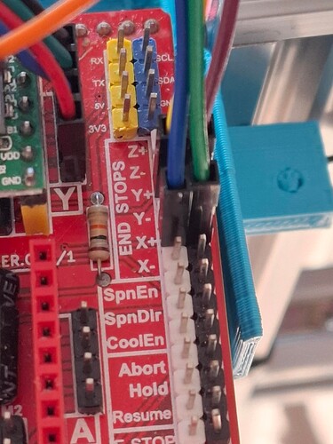
Hi, I’m trying to work on getting the homing working as you said above, Ive gone back to the basic/original software by Quarterpound to start from scratch. I’ve added a picture below of the wiring to the ‘x’ and ‘y’ endstop pins just to verify its correct, initially a week ago I had it incorrect until I realised x+ and x- are actually bridged and the same for the ‘y’ pins and after researching the cnc board in other forums I believe I now have the microswitches wired to the correct pins. There is 4 combinations of micro state and home input level, N/O hi or low and N/C hi or low, I cant figure out which one is correct for my application so have tested the lot.
During the testing this is what I’ve found so far,
cmd I used - rotctl -m 202 -r/dev/ttyACM0 -s 9600 -vvvvv also tried 204 which activates easycomm 3
Microswitch NO and endstop set to HIGH in code, it didn’t go through the homing sequence, however when it asked me for rotator command the rotator actually turned, P 90 30 actually got it moving AZ 90 and EL 30 was sent by Hamlib to Arduino however the functionality on the rotator axis was reversed, it turned 30 degrees and elevated 90, the wiring is correct I’ve triple checked it, in the end I swapped the CNC board x and y drivers over so that ‘x’ is now azimuth and ‘y’ is now elevation by swapping the nema17 motor plugs. P works, p works, K works etc, but there is no sign of it homing. It was impressive watching it operate via manual command but still not correct.
The other variations of NO/NC/HIGH and LOW The rotator seems to get a startup like its trying to home but there was no logic to what it was doing, at certain times when the endstop activated the microswitch on elevation the elevation stopped as though it had homed ok, but still I’m not sure if that’s how it works, but the azimuth endstop would trigger the micro on the Azimuth but the rotator would keep on going for another maybe 90 or 270 degrees depending on combination, BUT none of these variations allowed for any rotator commands to operate the rotator, hamlib was sending them but nothing was happening and like you said above it could be due to an error in the homing process but i cant see any errors. Also if i did a ‘p’ to get a location it came back with negative values of degrees or just through an error.
Below is the page I’m following for instruction but I’ve found not all of this content is the same for my scenario, I am also going slowly through code to understand it better.
Is there anything obvious I’m missing, thankyou.
https://wiki.satnogs.org/SatNOGS_Arduino_Uno/CNC_Shield_Based_Rotator_Controller
As you have noticed, if the rotator is in the home position, it doesn’t move and gets ready pretty quick.
This can also happen if you have no switches connected and configured the inputs to match the state of activated, this depends on how the board is configured. pull up/down and the home state setting.
I know for a fact that these CNC boards do deviate from the designs floating around, I have one where the STEP and DIR pins are swapped, and there seems fo be additional oddities with them. Like how the microstepping jumpers are going to GND or VCC.
If the motors go the wrong direction, simply rotate the 4-pin connector 180 deg (:
As this is a Uno hat, use a DMM to trace the pins to the MCU board to be sure of the pinout.
When testing, use a terminal directly to the rotator and skip rotctld, one variable less. It is possible to run custom commands with the rotctl command w, I haven’t tried it but for example w VE should work.
For communication test, use VE. Then to get the state and error use GS and GE commands.
Again, the firmware does not respond while running the homing, it will be buffered until it is completed.
