Looking at the build documents at https://ohai.satnogs.org/project/satnogs-rotator-v3-mechanical-assembly/hardware/ there is nothing in the documentation that shows where the main board (with the Arduino) goes within the housing. Is there any documentation on that step? Also, there is no documentation on how the motors wires, the IR sensor nor the magnetic pick are connected. Obviously I am missing where that documentation is. Can someone point me to it please?
I’m building a version 3.1, so not sure about the 3.0.1 one but think the frames are identical. Im either going to mount it under the frame lip (if there’s enough clearance on my rain guard and nema is thin enough) or down below somewhere.
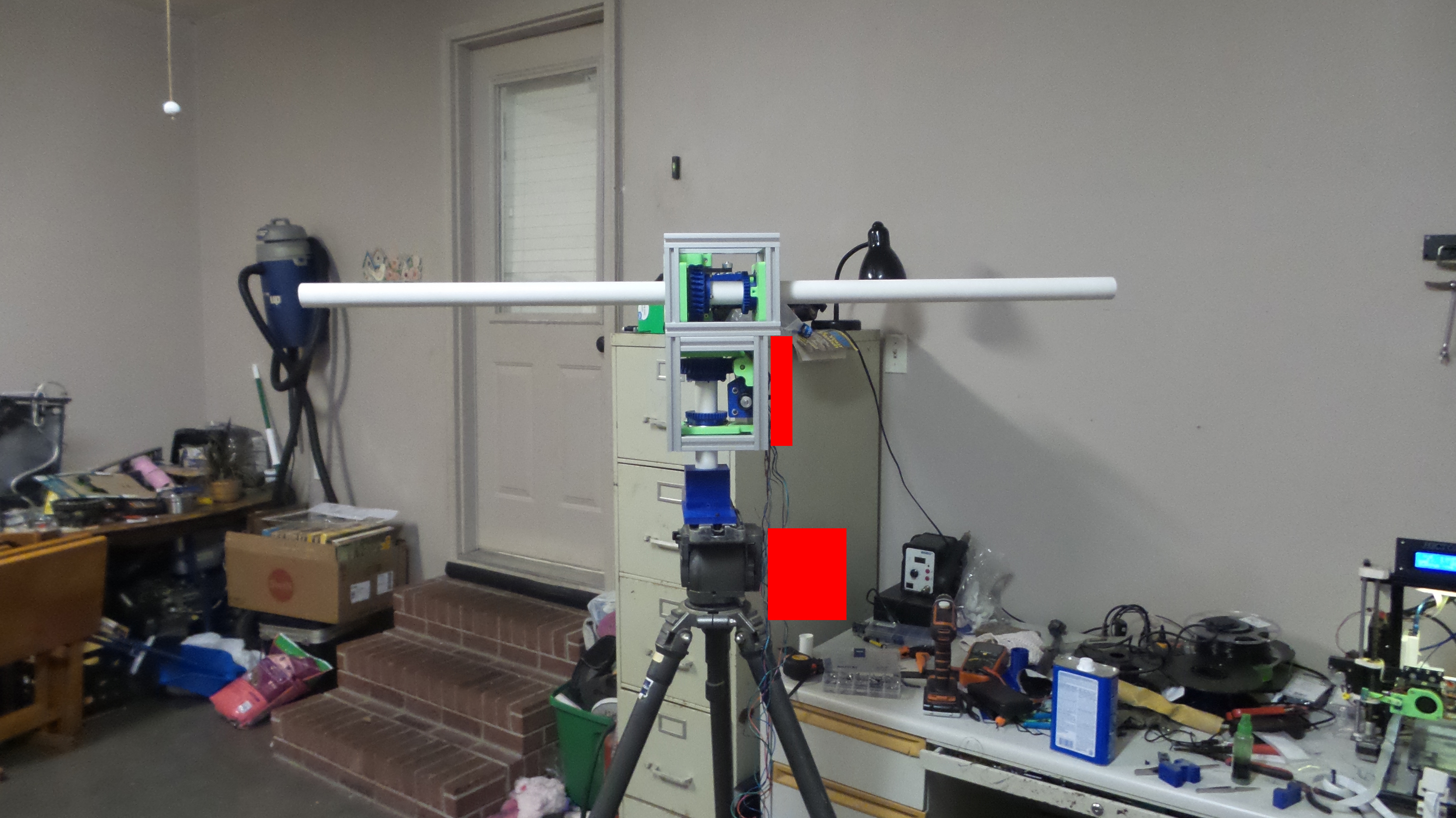
Mine is on the upper red box, inside a generic plastic enclosure the through hole connections line up in the slots on the upper part and the drilled on the lower to line up with the slots
Jason - yes, that is the very PCB that I am building up. I had the old board (and parts) but then it has sat in my garage for the past six months because of frustration at the documentation (or lack thereof) and never got finished.
Jason/Alex - I just went ahead and ordered the box within the BOM (looks like it is coming from Greece near as I can tell) so it should be here in a couple of weeks. I couldn’t find one on DigiKey nor Mouser.
My new PCB has been shipped (OshPark) so it should be here early this week. I had to order the DC-stepper controller IC’s off of eBay as well a well as a few more parts from DigiKey. Going to the next mechanical version (getting rid of IR sensor) Jason had to send me the part number for the end-stop switch. That needs to be added to the BOM - which I can do. Once I update the BOM, who or how do I get it added to the project as an update?
I guess my biggest complaint of this project is that I spend so much time looking for a single nugget of information that it gets frustrating. Having said that, I would be more than happy to work on some documentation (mechanical or electrical) to help out and return the favor of Jason and Alex helping me with this build up…I especially like the old mechanical build up documentation so I could do something like that. Since I am in the US, I have to have the shims and such to account for the metric to US conversion, so that would probably be a big help for us US guys. Who do I talk to about volunteering for this?
Having said all that ------ What can I do that would help the project?
I’d agree with you in part @herbsims, I found the mechanical docs fine but the rest need a bit of work. I have access to the documentation platform so can help with that. The paying job needed a bit of extra attention over the last few months, that will die down again soon. My thoughts are that the docs could do with a good spring clean with a similar approach to what has already been done. That is few words and more pictures.
It seems that the majority of frustration is in and around turning a mechanical device into a working electro-mechanical device. In other words making everything work together.
One thing you might look at if you’re using US / Imperial parts, is this site. I never tried it, I just crudely modified my own parts, but looked promising.
Hi @herbsims – like @g7kse, I also have access to the documentation site (https://ohai.satnogs.org), and I agree that a spring cleaning would be great. If you haven’t already, you may want to contact the devs on IRC/Matrix to ask about how best to contribute; I’ve helped a bit with the antenna assembly instructions, as that’s what I’ve built so far…the rotator is next on the list, but I haven’t jumped in yet. It would be great to take the knowledge you’ve acquired and make these docs better.
I just shot you a email with what I have figured out. I still dont know what pins on the raspberry connects to the satnogs controller, and also what the startup procedures are with and without the raspberry pi connected. Is the rotator supposed to home or anything first? Lots of questions and little answers. I also asked how you download and install the PI image (I’m a PI Noob)