AIS-gPPT3-1C Propulsion Module - First Integrated Open Source Thruster for PocketQubes

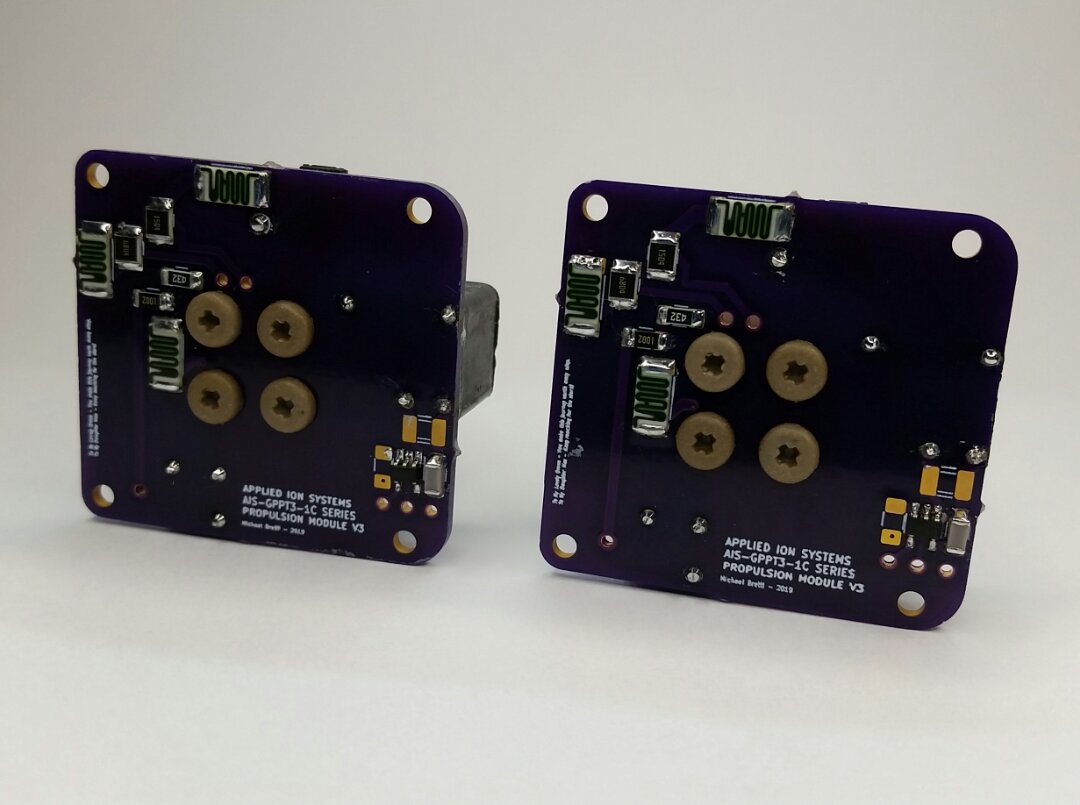
Greetings to the Libre Space community. This is really my first official post here. I am finally at the point where I can start sharing details of my work with the broader open space community. If you haven’t already been following my efforts on social media, I am currently working on the first and only open-source home-based advanced electric propulsion program out there, with a specific focus on developing open-source, ultra-low cost electric propulsion technology for PocketQubes. I literally design and build thrusters on the dining room table, and fire them in the basement! I started my high vacuum system build over a year ago, and began my first propulsion designs at the beginning of the year. This past Friday, I successfully tested for the first time my first completed, fully integrated open-source propulsion module for PocketQubes: the AIS-gPPT3-1C, a unique sub-joule micro pulsed plasma thruster (PPT).

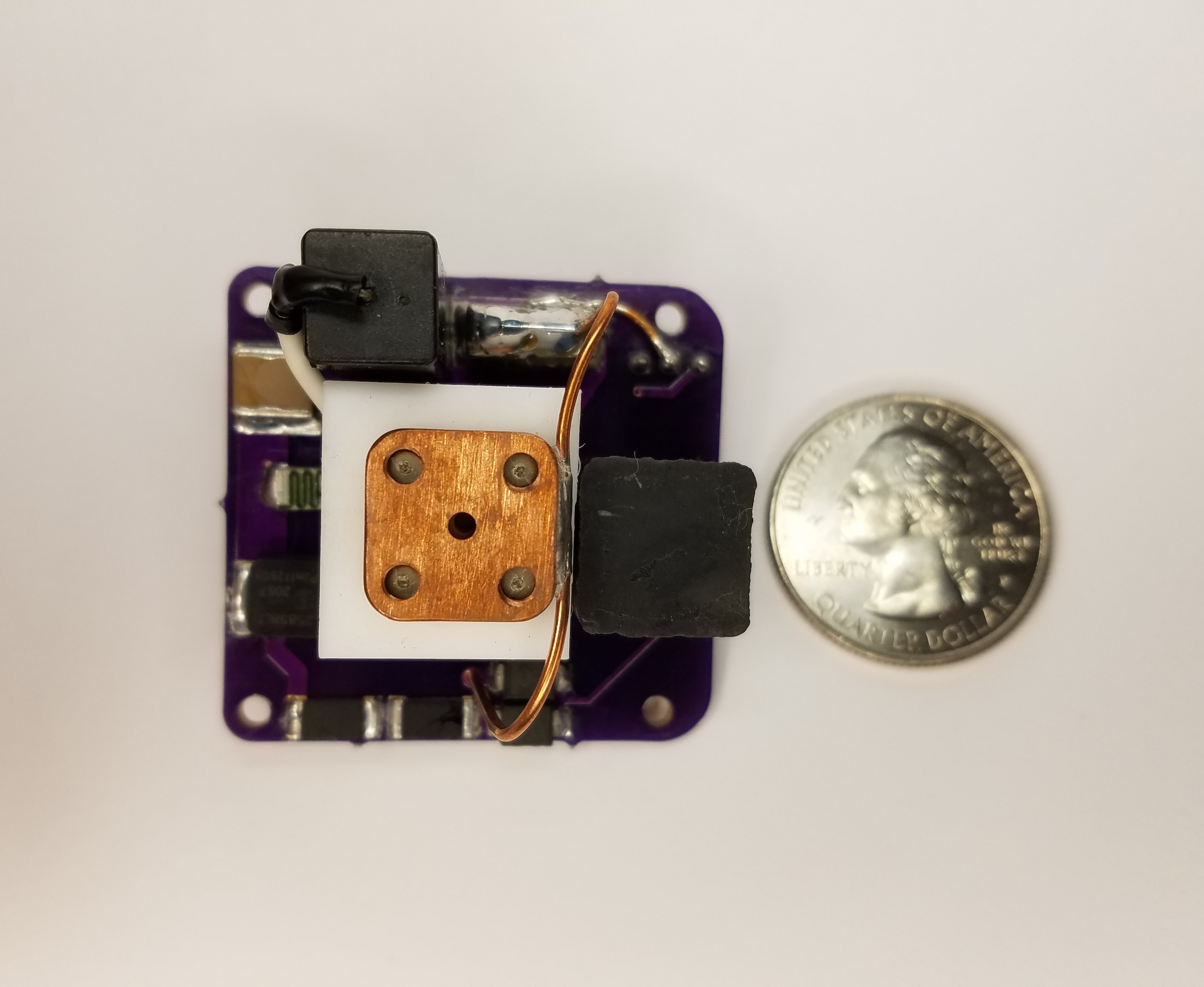
This thruster is made to be completely compatible with PocketQube size and power restrictions. Currently, there is no propulsion available for PocketQubes, making this the first system to be available for this class of satellites. Total dimensions are 40mm x 38mm x 24mm, with a peak power draw of 825mW, and average power draw of 163mW (simulated, still needs to be measured). Final mass is 34 grams. The thruster is sized to be used down to 1P PocketQubes.

The onboard electronics can be directly powered from PocketQube 3.3V power. A simple HIGH/LOW logic command is used to enable the high voltage supply. A logic pulse is used to directly trigger the igniter, which is driven by a sensitive gate thyristor. The circuitry boosts the voltage to 1kV for charging the main 0.2uF capacitor bank in 3 seconds. Simultaneously, a 0.1uF capacitor is charged to 300V for the igniter circuitry, which dumps this energy into a pulse transformer to deliver 5kV pulses to the igniter to trigger the main discharge. Nominal repetition rate is 0.33-0.25Hz.

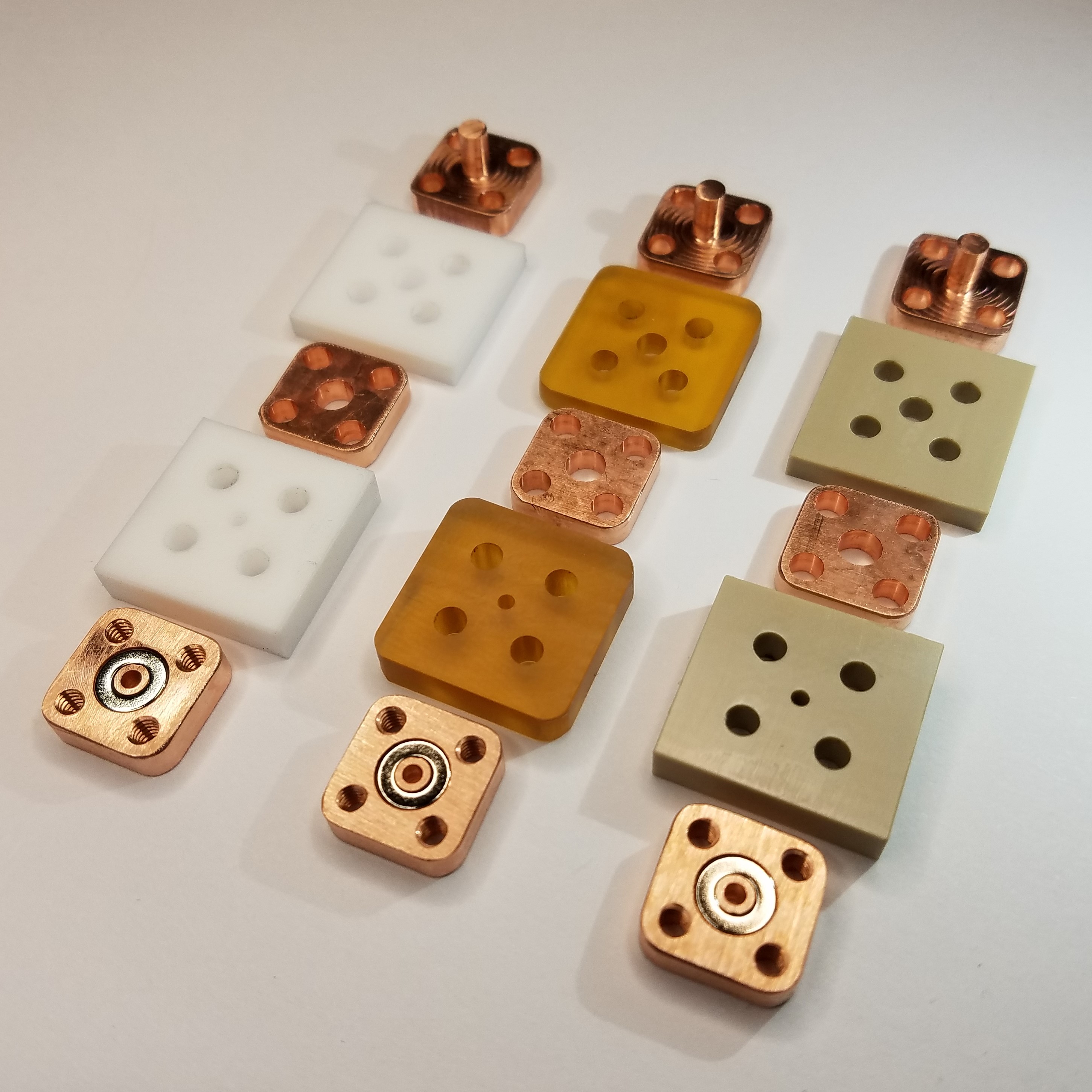
Currently, I am exploring ways of optimizing performance at the incredibly low energies the thruster is operated at. There has been some limited work in the past for small sub-joule pulsed plasma thrusters, but this thruster takes the field to a new level. Total energy per shot is around 0.09J, making this potentially the lowest energy PPT ever designed and fired. I am in the process of exploring new fuels in addition to classical Teflon, including Ultem, PEEK, and Bismuth-Tin. The first three listed fuels can be seen assembled with the electrodes:

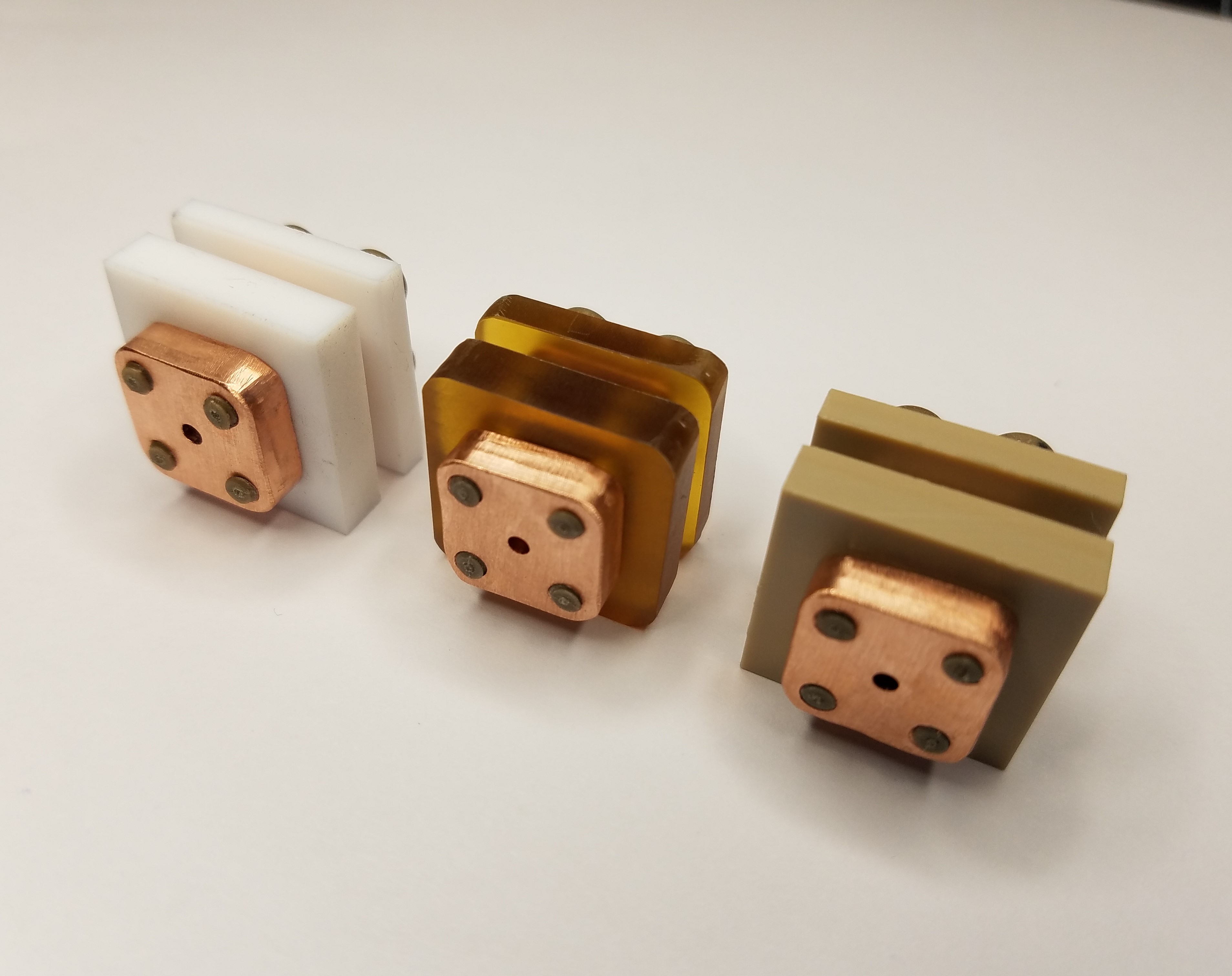
The thruster itself is made with a highly unconventional topology using flat-stacked plates to minimize space for the incredibly tight requirements for PQs. The design is kept simple to make the thruster cheap and easy to assembly.

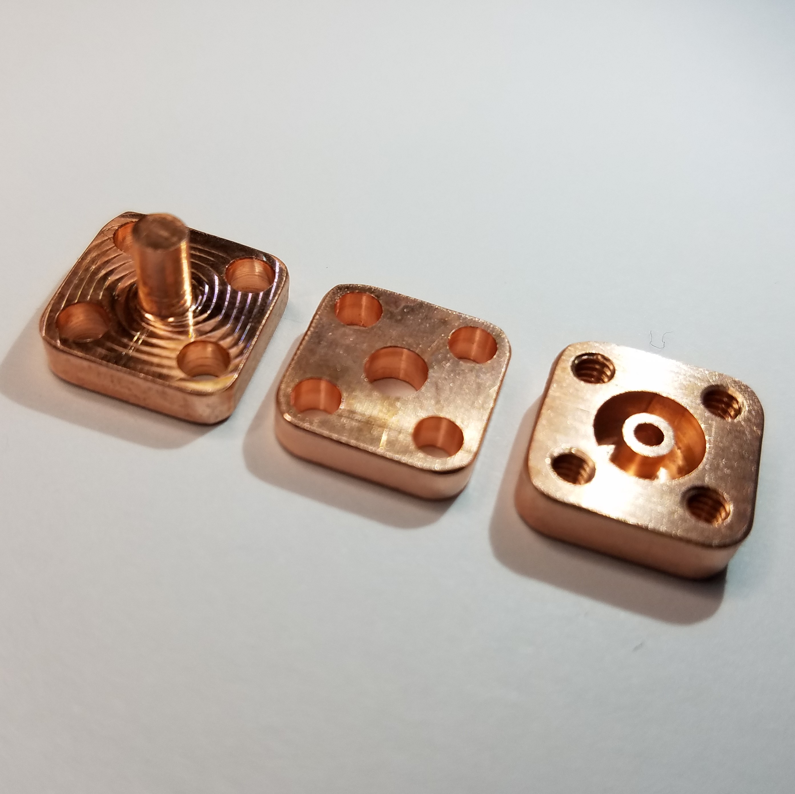
Another unique feature of this thruster is the use of an embedded high-strength permanent magnet in the anode output plate to act as a magnetic nozzle to increase thrust. Work on a related thruster technology in literature, Vacuum Arc Thrusters, has shown that magnetic nozzles can increase thrust gains by up to 30%. Since this thruster operates in an electrothermal mode of acceleration, rather than typical electromagnetic acceleration seen in larger, higher power, and diverging electrode PPTs, the magnetic field can be used to accelerate the electrothermal portion of energy. As far as I am aware, this is also the first time an integrated magnetic nozzle has been used with such a low-energy PPT, and fully integrated into the structure.

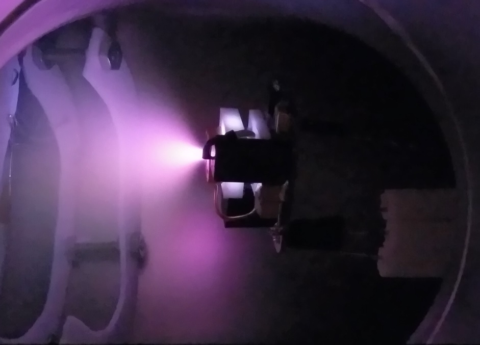
Here you can see the thruster firing in my high vacuum chamber. Vacuum level was 1x10^-5 Torr. The thruster module was powered and controlled externally with an Arduino Uno with 3.3V and control signals from the Arduino. In the captured shot of the thruster firing, you can see a beautiful pink plasma plume emanating from the thruster, which also partially illuminates the Teflon fuel from the inside. Video of actual operation is on social media, and I will be uploading it to my website and Youtube soon.

Overall this has been an immensely challenging task, resulting from hundreds of hours of research, design, preparation, and testing, but is still only the beginning. The thruster will undergo full testing to determine impulse-bit, thrust, and lifetime, eventually looking towards ion velocity measurements and plume discharge current as well down the road. I have already performed impulse-bit measurements on the prior prototype thruster, the AIS-gPPT2-1C (tested with external HV supplies and not with integrated electronics) with a simple micro-pendulum stand I built. My next upcoming test will be performing impulse-bit and first lifetime tests on this new thruster with the Teflon fuel.

The thruster has already achieved many firsts in the field of propulsion, and is breaking down barriers for accessibility to ultra-low cost open source propulsion. I upload complete information of everything I do in excruciating detail on my website, http://appliedionsystems.com/. I plan on continuing these efforts and further developing more electric propulsion for PocketQubes and even Cubesats, looking at cost reduction over an order of magnitude than current propulsion solutions on the market (as of now, none yet for PocketQubes besides this). I already have the V2 design complete, allowing for direct analog reading of the main bank and igniter bank voltages to determine thruster firing in space, as well as pulse counting, lifetime, and other pulse measurements.

Besides developing new thruster technology for these class of satellites, I want to lower the barrier of entry in the field, and make propulsion more accessible, by using a unique open-source approach to propulsion, and actively engaging the community with full details of the builds. I will eventually be moving towards full live-streams of thruster tests as well. You don’t need millions of dollars, massive facilities, a PhD, or crazy state-of-the-art tech to do advanced propulsion research! Advances in space technology and propulsion CAN be accomplished in an open-source manner, even at home!

26 Likes

Thank you for sharing. I for one find this fascinating purely from an experimenter’s viewpoint. Excuse the dumb question. So what is actually coming out of the ejector? Ions right? There would be no point of ejecting electrons as they have very little mass so assume these Ions have a positive charge and mass due to protons and neutrons. Action and Re-action produce forward movement in a vacuum?
Very interesting. Just thinking of all the possible applications.
73 Bob vk2byf

3 Likes

Not a dumb question at all! For these types of thrusters, a plasma is created and blasted out the back as a plume. The plasma is a neutral mix of both ions and electrons, and the composition depends on the fuel used. For example, since teflon is used in this current version, a mix of Carbon and Fluorine plasma is released. Plasma thrusters are a bit different however from ion thrusters. Where a plasma thruster emits a plume of neutrally-charged plasma, an ion thruster (like Hall effect, gridded ion, or electrospray), emits a beam of ions, which is externally neutralized by an electron-emitting neutralizer to prevent charge build-up on the spacecraft.

The plasma plume from this thruster does exert a force, albeit small, on the order of about 1uN or less! However, for such small satellites like PocketQubes, not much force is needed in space to get them moving. With propulsion available for PocketQubes, a whole range of new capabilities can be explored, increasing their utility and mission capacity.

7 Likes

Thanks for your explanation which, with me, usually raises more questions.
So your fuel, Teflon, will eventually be used up and the thruster will stop working?
What sort of working life time do you anticipate you can get at these micro Newton force levels?
Interesting point about having to prevent the building up a charge on the space craft. Everything is different in space and has to be dealt with differently to what we can get away with on earth.
Interesting too how we can use the sun’s emission to rotate a Cubesat simply by having a shiny side and a dark side. Kind of re-enforces the idea that light, electro-magenetic radiation, can be a particle and/or a wave.
What is a photon exactly, is another one I can’t quite get my head around so I satisfy my curiosity for now by thinking of it as a burst or packet of electro magnetic radiation.
I’m nearly 70 but still learning.
Thanks, Bob

3 Likes

In theory, assuming a perfect world, yes, the teflon fuel will eventually be depleted enough that the thruster will not produce any meaningful thrust. However, there are numerous failure modes that can occur in these thrusters. One is erosion of the igniter. A second is main cap bank failure. For my previous gen-2 thruster, the cause of failure was actually carbon charring of the teflon fuel bore, eventually causing the thruster to short. This however was caused from excessively high energy deposition compared with the fuel surface area. You need to find a good balance between discharge energy vs ablation rate and total surface area - too little will produce too low thrust, too high and you end up charring the fuel rather than producing additional extra thrust, decreasing lifetime.

For my previous version thruster, lifetime was limited to 500 pulses due to carbon charring. However, the igniter and electrodes suffered almost no erosion, and very little of the fuel was actually used. My goal for the newest thruster is at least an order of magnitude more, with a goal of eventually 10k pulses. Part of why I am exploring other fuels is to see if I can achieve higher lifetimes by reducing the total ablated amount per shot, which will sacrifice thrust but increase lifetime. It’s a challenging balancing act. I am also hoping to confirm if the embedded magnetic nozzle will help compensate for this loss and increase thrust passively.

Normally, large commercial PPTs can be rated for over 1 million pulses. However, we have to consider the incredible size and power restrictions of the PocketQube frame. This limits the total fuel that can be reasonably used without additional feeding mechanisms, as larger PPTs often use spring loaded feeders to constantly feed in the large Teflon fuel bar as it is ablated. This is by far the smallest complete PPT module that will be available on the market for the community, and while it is much cheaper and simpler, and opens up propulsion for PocketQubes, it does come at a price. The major price here is lifetime for now. But it’s a problem I’m working on improving!

Never too old to keep learning! Part of my goal is to make propulsion more accessible to the community, and provide resources for enthusiasts to learn more about this technology, so ask away!

9 Likes

Been quite busy over the past few weeks with some exciting developments on the propulsion system. I have finally completed the first round of impulse bit testing of the new AIS-gPPT3-1C thruster. So far, it looks like shot to shot consistency is very high and improved over prior iterations. Average impulse-bit is around 0.65uNs, which at 0.33Hz correlates to a thrust level of 0.22uN.

Unfortunately, after shot 130, the thruster stopped firing, which was traced back to the main cap bank failing and shorting as a result. This was anticipated, since the caps I selected were not pulse rated, using standard X7R dielectric. I have since upgraded the caps on the board to Kemet MLCC high voltage pulse rated SMT capacitors. These new caps use C0G insulation and are rated for extreme environments and pulse detonation applications, with extended temperature range and stability. The new V3 of the electronics board will actually be here tomorrow reflecting these upgrades, which should hopefully solve any major lifetime issues with the boards.

Looking at performance trade-offs, I may also decrease the overall bank capacity from 0.2uF to 0.134uF, which would decrease shot energy from 0.09J to 0.06J. However, this would allow me to run at 0.5Hz, reducing peak power consumption to only about 550 mW (small fraction of a second during charging cycle), with average power draw at 113 mW, and based on anticipated performance scaling, would have a 69% increase in thrust to 0.32uN.

In addition, I have officially partnered with Fossa Systems on an incredibly exciting and potentially groundbreaking open-source PocketQube mission, where we will be testing this propulsion module in orbit. If successful, this would be the first time an open source, fully home-built and engineered independent electric propulsion system has ever flown in space, and could possibly be the first PocketQube to ever successfully fire propulsion in orbit. This would also mark a major advance for the open space community, flying a quite advanced fully open-source internationally-collaborated PQ mission with on-board propulsion.

In preparation for this joint collaboration, I will be testing and delivering a set of my newest thrusters to Fossa Systems. Over the course of the next week, I will also attempt to live-stream the qualification tests of the new thruster design on the Applied Ion Systems YouTube channel, broken down into ~3 hour tests over the course of several days. I will update and release scheduling info on the Applied Ion Systems Twitter. This will allow anyone to tune in and view the thruster firing and lifetime tests real-time.

11 Likes

@Applied_Ion

Wanted to say a quick thanks for coming to OSCW and presenting, Michael! This is amazing stuff, I love the DIY physics that you are bringing to this community.

Anxious to track the thruster’s use in orbit!

8 Likes

Corey Shields,

Thanks! I am extremely grateful to have been able to attend and present at the workshop! Really amazing and fantastic event with amazing people! Some very exciting times for the community indeed!

4 Likes

Tons of new details since the last time I posted last month. I implemented the changes with the new C0G pulse capacitors at reduced bank energy, and successfully ran my first two propulsion livestreams. During these tests, I significantly over-drove the pulse capacitors (which are rated for nominal 1kV operation, at a max of 2kV briefly). I actually skipped testing the V2 board design, and went straight to V3 since changes happened so fast to the design.

For the first test, I ran the system at it’s nominal voltage of 944V for about 236 pulses, which began having difficulty with ignition (due to lower igniter bank voltage since this is tapped off the main high voltage rail output). I then raised the voltage to 2kV for the remainder of the test (5V in), which resulted in catastrophic failure of the capacitor after another 500 pulses.

For the second test, I drove the capacitor at 1.5kV (4V in), which resulted in much longer lifetime, but still eventual failure of the new pulse capacitors. The thruster successfully completed 5.33 15 minute orbital firing cycles with 5 minute cooldowns in between, before the main bank shorted and failed. Rep rate was between 0.29-0.33 Hz for the 15 minute cycle duration. Input voltage was kept at 4V for the duration of the test (corresponding to about 1.5kV on the main bank. A total of 1232 shots were counted, highest shot number yet for a test. The lower and upper bounds for successful ignitions is between 78-91%. For the 15 minute cycles, total ignitions were very repeatable, around 220-240 per cycle.

At 4V in, peak current draw during the start of each charging cycle was 150mA, for a peak module power of 600mW. Standby current draw was around 90mA, for a standby power of 360mW. Shot energy was around the 0.15J range per shot. Although the main bank died, it was confirmed that reasonably reliable ignition can be achieved with the designated 4V bus input from the battery supply, even after several thousand shots, with the ignition voltage greatly increased as a result.

Upon inspection of the thruster, the Teflon fuel still has no charring in the bore, and no measurable change in diameter. Total shots to date on the board (minus the cap) and thruster stack is 2098 shots. It is now very clear that the sole bottleneck for lifetime at this point is the main discharge cap. Reducing voltage allows for more shots, but still fails well below the projected total fuel lifetime of 100k shots. Fuel and electrode erosion at this point are not factors. Reliable ignition can be achieved however by increasing the igniter bank voltage, which does not appear to affect the igniter cap longevity, due to the significantly lower pulse current it delivers. This is easy to do with a single resistor value change on the board.

Going forward, the following changes will be implemented:
1.) Driving the main bank at much less than 1kV for extended pulse cap life, around 800V, possibly lower for 3.3V in.
2.) Increase the igniter bank voltage from 350V to at least 600V, which has shown very stable and reliable ignition at this level for 3.3V in.
3.) Reducing the main bank capacitance further to increase charging and repetition rates for lower impulse-bit, but higher overall thrust at reduced power consumption.
4.) Swapping out the EMCO Q20-5 for a lower voltage output, higher current module to balance circuit performance with the above changes.
5.) Completing the new V4 board with slight change in primary capacitor bank mounting topology.

In addition to testing, I have successfully completed the two first prototype flight modules of the AIS-gPPT3-1C V3 propulsion system to be sent to Fossa Systems for integration, which can be seen below:

I released the schematics and BoM for the V3 board, and will be uploading all of the files to my website soon. Note however that the V4 system will be different from this slightly.

Finally, I have begun working out the preliminary details for new thrusters at this level. This includes both open source PocketQube as well as CubeSat propulsion, looking at both attitude control and primary propulsion, continuing to explore solid fuel pulsed plasma thrusters, as well as liquid fueled pulsed plasma thrusters, electrospray, and RF plasma.

10 Likes

Thanks for the update.
Seems like your main problem is the dump capacitor.
What sort of value of capacity are we talking about and
what material is used to make this capacitor?
Obviously you want as many nano farads as possible
but you are restrained by the space available.

Just curious Bob
“When you stop learning, you start dying”. A quote from Albert Einstein.

4 Likes

Bob,

Thanks for your questions. The value for each of the main bank capacitors is 0.068uF - with 2 in parallel, that gives me a total capacitance of 0.136uF. The capacitors are MLCC ceramic caps made from C0G dielectric and are specifically rated for high current pulsed applications. While upon first glance it may seem I want as high capacitance as possible, that may not actually be the case due to the available power. While higher capacitance gives more energy per shot, and hence higher impulse bit, for the limited charging capacity I have at such low power levels and small size, I can only charge them so fast. Thrust is frequency x impulse-bit, so at lower frequency, the thrust is lower. I started out at higher capacitance and higher shot energy, but have actually been decreasing total capacitance with each iteration so I can increase the rep rate to get higher total thrust.

The big constraint for this thruster is space as well as power. It is very difficult to find high voltage pulse rated capacitors small enough to fit within the volume required for such a tiny PQ thruster, and I am using probably the smallest available HV supply on the market, which has the cost in low charging currents, forcing me to make some design trade-offs overall.

4 Likes

Thanks, it’s a delicate balance or compromise to get the job done. I’m afraid the mathematics leaves me behind now even though I had to learn all this about 55 years ago as a apprentice electronics technician.

Any ideas how much effect a single shot or a series of shots has on changing the velocity of the actual cube sat in the not so perfect vacuum of space? Can you even measure such a small force. You have mentioned micro Jules in one of your previous posts.

What about the affect of the change in temperature?
From reading telemetry of some of the cube-sats in LEO the temperature swing seems surprisingly low at about +25C to -25C. I was expecting to much colder. Even this relatively small moderate change must put some stress on “off the shelf” components.
These number are from one side of a cube sat to the other so I suppose some of the heat from the hot side would move to the cold side by conduction.
Cheers Bob

5 Likes

Bob,

In terms of the effect of the shots on velocity, I can at least say that a single shot would be negligible at LEO. The force we are looking at here for this thruster is sub-micro newton, probably in the range of around 0.65uNs (which will decrease as I lower bank capacitance). For Cubesat attitude control, I believe that this thruster is still enough to do precise rotational maneuvers (with a series of many shots) since the specs are comparable to a few prior launched Cubesat attitude control PPTs I have seen in literature. This thruster definitely would not have enough delta-V as main propulsion for a Cubesat however. For a PocketQube, I am aiming for it as main propulsion (or as at least an experimental payload for low-cost propulsion testing for PQs), but I will need to get the thrust and lifetime up much higher. Realistically to see any effect at this level, the thruster will need to continuously fire for quite a while, but how much, I can’t say for sure. Really goes back to simulation and field testing.

For changes in temperature, this is always a concern for any subsystem. Fortunately for the thruster, the circuitry is actually quite minimal, and I tried to spec out as high tolerance and temperature range components as possible, either aerospace or automotive grade. I don’t think thermal cycling from +/-25C should be an issue for the system, though it still needs to be tested via TVAC. Both of the modules I will be sending to Fossa Systems will in fact undergo TVAC testing, so we will know fairly soon how well they do. I also presented a simple TVAC concept design at OSCW 2019 for an insert-able TVAC shroud for my vacuum system which would allow me to thermally cycle the thrusters while firing them in vacuum, but I just don’t have the funds right now to implement testing like that. Hopefully though I would like to implement this and other testing (like vibration and radiation) myself, and maybe even offer low-cost testing for the community as well, but this would be well down the road (unless I manage to get a large funding boost to accelerate these and my propulsion efforts for the community).

5 Likes

Very interesting, I’ll be keeping an eye on the topic to see your progress.
Cheers Bob

1 Like

Excellent project, I have been following and analyzing it.
When do you think you may be testing a PQ in space?
What would the monitoring of this system be like? Do you already have a telemetry system selected and dedicated?
Thanks!

1 Like

Ricardo,

Thanks for your feedback. The thrusters will be tested in a joint collaboration between myself, Fossa Systems, the Libre Space Foundation, and Amsat. They will fly on two PocketQubes sometime early next year, though the official launch date and mission details have not been publicly released yet. They will be handling all of the telemetry, monitoring, and communication details. I believe we will be looking at both orbital changes as well as monitoring the two feedback pins on the thruster. Ignition should be confirmed if both the main bank and igniter bank voltages drop to near zero (representing successful ignition and firing of the thruster) after the trigger command has been sent. Hopefully I will have more details to share as we approach closer. I know at least we should know about the thermal testing results first, then vibration, and successful integration and firing on their sats in their test chamber in the coming couple of months, so I will definitely be updating info as it comes in!

3 Likes

Just a quick update on the progress of the gPPT series thrusters. I recently completed the V4 design and got around to testing it. Unfortunately, I could not achieve ignition, and reviewing data, scaling trends, and everything going forward, I made the decision to retire development on this series of thrusters. Unfortunately, it is apparent that a sub-watt, sub-Joule PPT cannot scale to provide the necessary required thrust for orbit keeping, de-obiting, or other orbital maneuvers. While the technology can still be used for attitude control for larger Cubesats, and as a great low-cost learning tool for others to get started with electric propulsion, the physics simply do not scale to achieve my initial goals of improving PocketQube orbital lifetimes. At the <1uN thrust level, it unfortunately does not work out, and I am ultimately limited in performance due to available power.

However, moving forward, I have begun several new phases for higher power thrusters for the PocketQube and small Cubesat level. I will be looking at the next power class of PPTs, as well as beginning to look at ionic liquid electrospray thrusters. In particular, electrospray has incredible potential at this level, and has historically shown to scale to provide significant thrust at very low power levels (1.5W), and can be used to achieve increased orbital lifetime of these smallest class of satellites. I will open up a new thread topic specifically for this electrospray thruster, which I have already released the concept design yesterday, and should be able to work out a functional prototype soon.

5 Likes

Thanks for the update.

1 Like

Sorry to hear about this (I’ve enjoyed following your progress). But at least you have a plan moving forward. Best of luck! (and I will follow your new thread)

–Roy
K3RLD

1 Like

Hi, I wanted to know if you have already opened the thread topic specifically for this electrospray thruster?Do you have a link? or how can i search it? Thanks