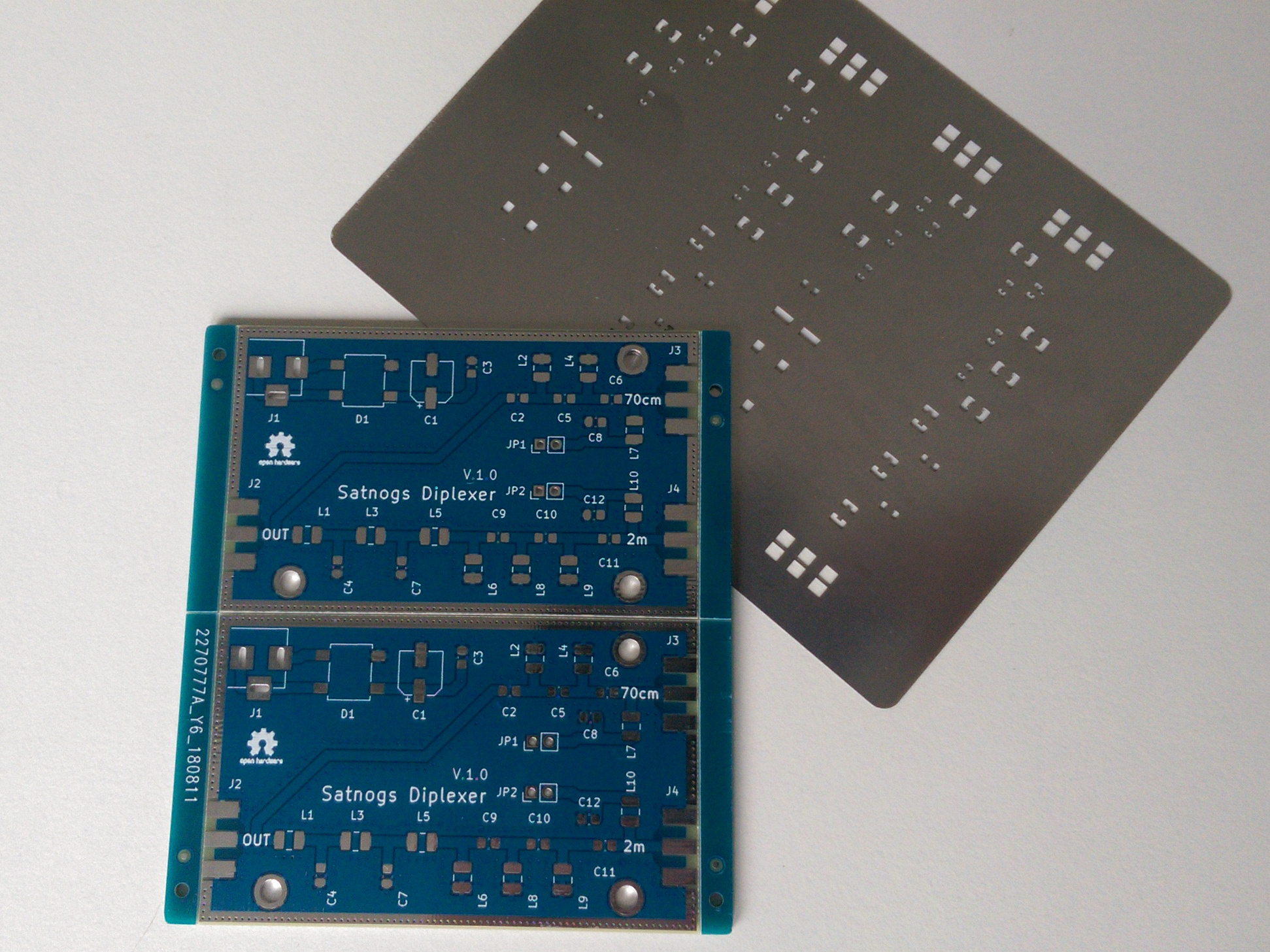
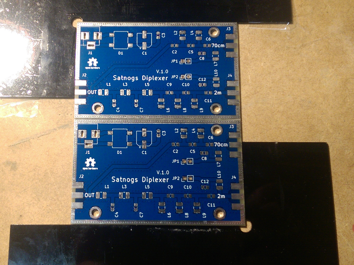
Okay something was wrong with the gerbers anyway … so I added the three mounting holes.
Now I should be finally able to order all the boards (four different design for various projects).
Hopefully they turn out all right.
Okay something was wrong with the gerbers anyway … so I added the three mounting holes.
Now I should be finally able to order all the boards (four different design for various projects).
Hopefully they turn out all right.
Short status update from my side:
Even-though I payed almost as much money on shipping than on actual boards and stencils,
I’m still waiting for them to arrive.
My last order was a lot quicker and cheaper. Might be a good time to switch board houses again.
According to the tracking, the pcbs are already at the airport in Frankfurt.
The last entry is ‘Arrived at facility’ from a few days ago so I assume that the German customs office wants to have a look at the shipment as well. (At least that has the reason for those delays in the past.)
I’ll oder the capacitors and inductors tomorrow, so that I can start assembly one for testing as soon as they arrive.
Which shop did you order them from?
I ordered at JLCPCB.
They were quite cheap in the past: 10 PCBs (up to 100x100mm and green soldermask only) for 2$ and stainless steel stencils for 7$, with cheaper/free DHL express shipping.
At at least that was the deal the last two times I ordered something there.
Prices for the actual PCBs and stencils stayed the same, but the cheapest shipping I could select
was normal DHL for 30$.
I tried ordering the three designs in the order separately, but the would have resulted in 16$ shipping per design.
I could have gotten the boards from dangerous prototypes/dirtypcb and a stencil from OSH Stencils, but with shipping from two shops plus the more expensive stencils it would have costed more.
In the end I payed something around 60$ for 20 diplexer boards (paneled with 2 boards per panel),
the diplexer stencil and 10 PCBs for each of my other two designs (for an unrelated project) plus an other stencil for those.
So it’s still rater cheap, just not as ridiculously cheap as my last orders.
Short status update:
The pcbs are currently held hostage by my favorite customs office.
So I’ll have to drive there, unpack everything for them tell them it’s just some 85340011000 and 73269098000.
Hopefully they’ll just type that into their computer and I can pay my import tax (~8€) and be on my way.
Last time I had to go there for pcbs they tried to figure out the correct tariff numbers on their own,
which took them about half an hour.
Then they decided to lectured me about why I’m not allowed to sell those PCBS in Germany.
I’ll try to show up last minute before their lunch break, so they’ll try to get rid of me as fast as possible.
That helped a lot in the past.
Update: TLDR; I managed to retrieve the PCBs from the customs office today.
Longer story for added comedy:
Sticking to my plan, I showed up at the customs office right at 11:00 just when the officers there started to thing about lunch break.
When I entered, everyone in the room was engaged in a vivid discussion about whether their stamps were worn down enough to justify ordering new ones, or if they just needed to switch to the softer, but more expensive stamp pads.
I had to clear my throat a couple of times until I was enough of a disturbance that some decided to take care of me.
After handing over my the letter from DHL, an invoice for the PCBs themselves and the Paypal receipt, I was accompanied to the post room where the officer started digging through a pile of parcels.
He ignored my helpful suggestion to try the pile labeled “China” until he was 100% certain that the pile labeled “Asia, misc” did not contain my parcel.
Then he continued to dig through the “China” pile muttering to himself about people always putting things into the wrong piles.
As usual I had to open the parcel and explain its contents, while the officer pretended to listen.
Next I was accompanied back into the actual office at pace of snail on caffeine withdrawal
in slow motion.
What followed was an epic quest for the right customs tariff identifier:
“Are those smart cards?” - “No those are printed circuit board comma multiple layers” - “Our system doesn’t know those.” - “Did you try 8534 0019 000?” - slowmo typing “That can’t be the right number it says something about printed here” - “Yes, the designation should read printed circuit board comma multiple layers” - “Oh right it does. What are printed circuit boards?” - me waving with a pack of PBCs “Those things.” - “Oh. Right”
After that I only had to pay the import tax, which means handing over a few euros and getting receipt consisting of 6 DIN-A4 pages which had to be stamped at least twice.
Anyway I have successfully and officially imported the 20 diplexer PCBs into Germany, pay my taxes and sat through all the paperwork like good citizen.
Also I’ll ignore the fact that the whole process intended to make me pay 10€ import tax did cost the government at least twice as much.
And yes they should swap out their stamps. It does look a little fuzzy.
I never thought I would say this but UK import duty stuff is far slicker (but far less funny). Grumpy man says ‘gimme the money’…hand over money…grumpy man throws package at you.
Looking forward to seeing them in action. Just out of curiosity do you screen print solder paste on the boards then place and oven bake? It looks like it to me and I didn’t know that kind of thing was hobby oriented
Depends on what you consider hobby.
I know a lot of hobbyists that ended up getting the equipment for reflow soldering.
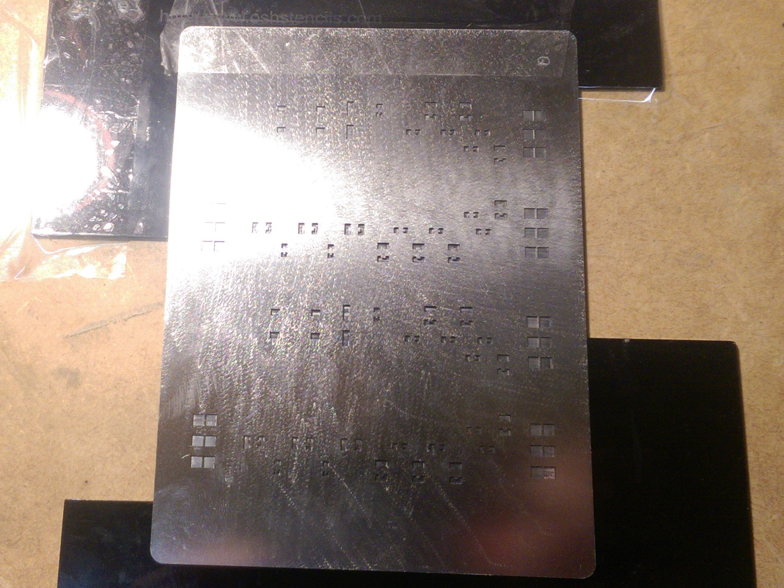
For single board I hardly go to through the effort of reflow soldering, unless there are some QFN parts on it (never got the chance to try out BGA but it’s on the bucket list), but if I need to assemble 10 or 20 identical boards reflowing is considerably faster.
In the past I used stencils cut on a friends vinyl cutter, but now that you can get cheap stainless steel ones that’s not worth the effort.
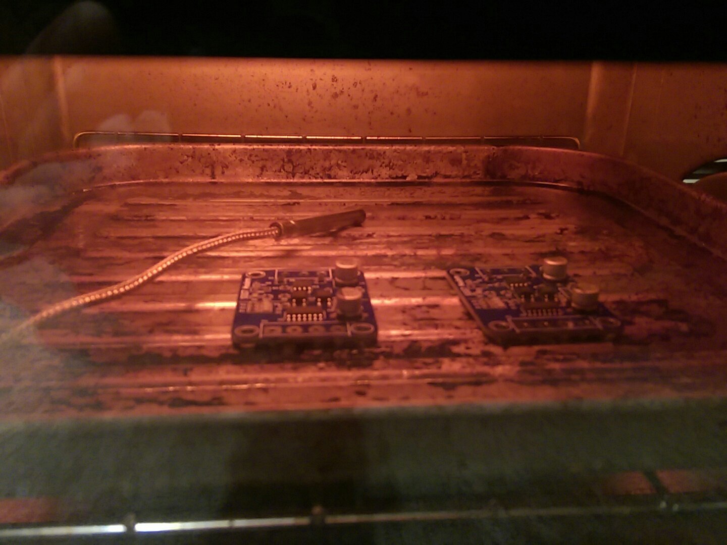
About two years ago I bought cheap toaster oven and bodged a temperature controller for it.
After some trail and error I’ve gotten to the point where I can solder batches of 4-5 boards,
with minimal manual cleanup in the time it takes me to do one with the soldering iron.
I can see the appeal. Especially with pre cut stainless masks. A loooong time ago I helped support variable height adhesive / solder dot printing development for double sided boards. Reflow one side and wave the other. Its obviously moved on a long way since then.
It makes me want to have a go myself. Perhaps I’ll put an oven on the christmas list 
Hi
I would be very interested in a board as well please.
amazing work!!
thanks
Brennan
We will see if it is amazing work if it actually works as intended.
I’m still waiting for the parts to arrive from my distributor.
It seems if they were suddenly and unexpectedly hit by the great MLCC shortage, just as I clicked the checkout button. (They claimed to have everything in stock when I clicked the add to cart button.)
Ironically the only part that’s not in stock is the 100nF capacitor used as bypass for the bias-tee supply.
I have reel of 100nF in 0603 hanging at my wall so I’ll try cancel that part of my order and bodge 0603 parts on the 0805 footprint.
This project has started to attract strange problems lately.
Status update number 5:
After strongly worded E-Mail my distributor agreed to deliver all available parts asap,
so I could start assembling PCBs today. At least that was my plan.
At that point I realized that was missing 4.7pF capacitors and 68nH inductors.
Trying to be a smart person, I wrote a script a few years ago that generates a CSV files from my schematic which can the be imported as shopping cart at various distributor websites.
A very smart person would have checked the resulting shopping cart afterwards, but since I was only trying to be a smart person I did not spot the two typos in the schematic preventing the capacitors and the inductors from ending up in my cart.
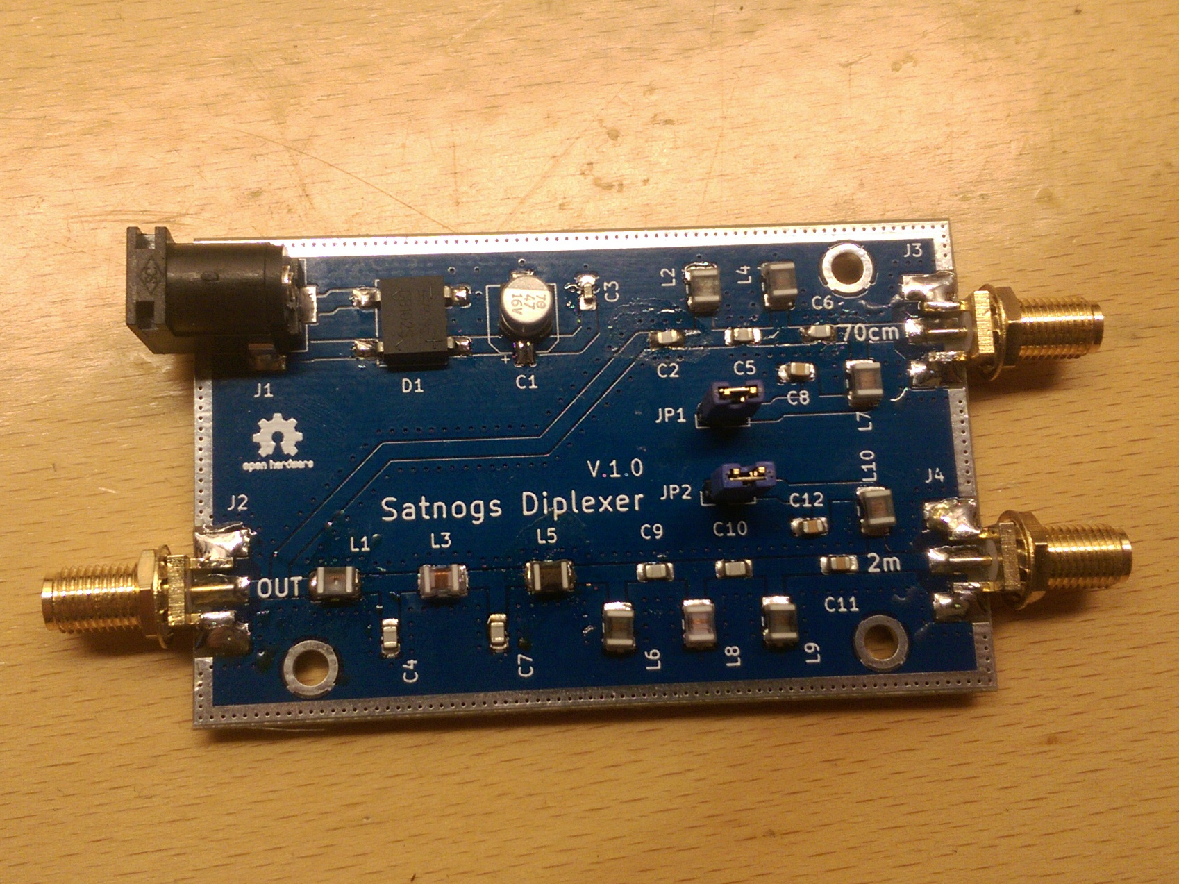
Fortunately I had a few 68nH inductors from an other filter experiment, so I could at least complete the 2m section on one board.
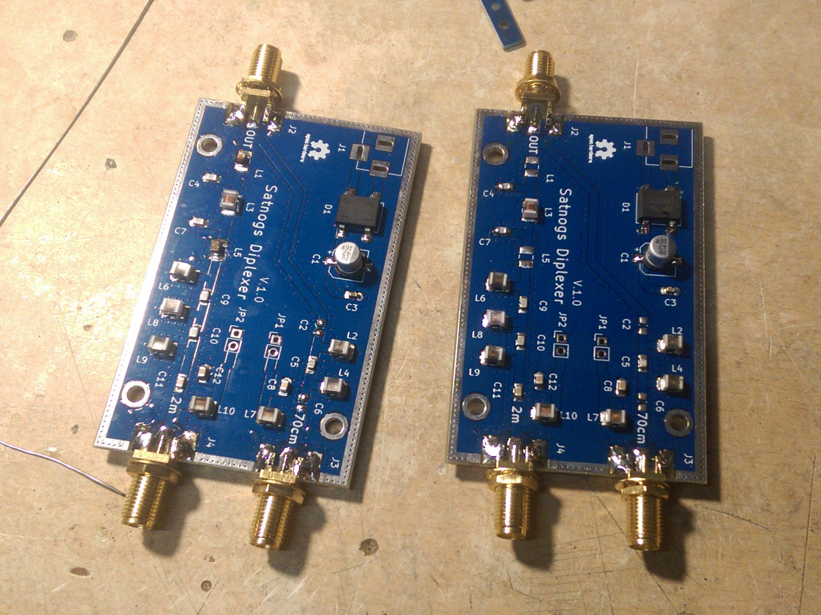
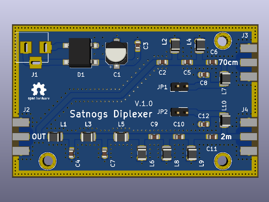
You should have also noticed by now, that the footprint does not perfectly match my SMA connectors, leading to a few ugly but functional solder blobs.
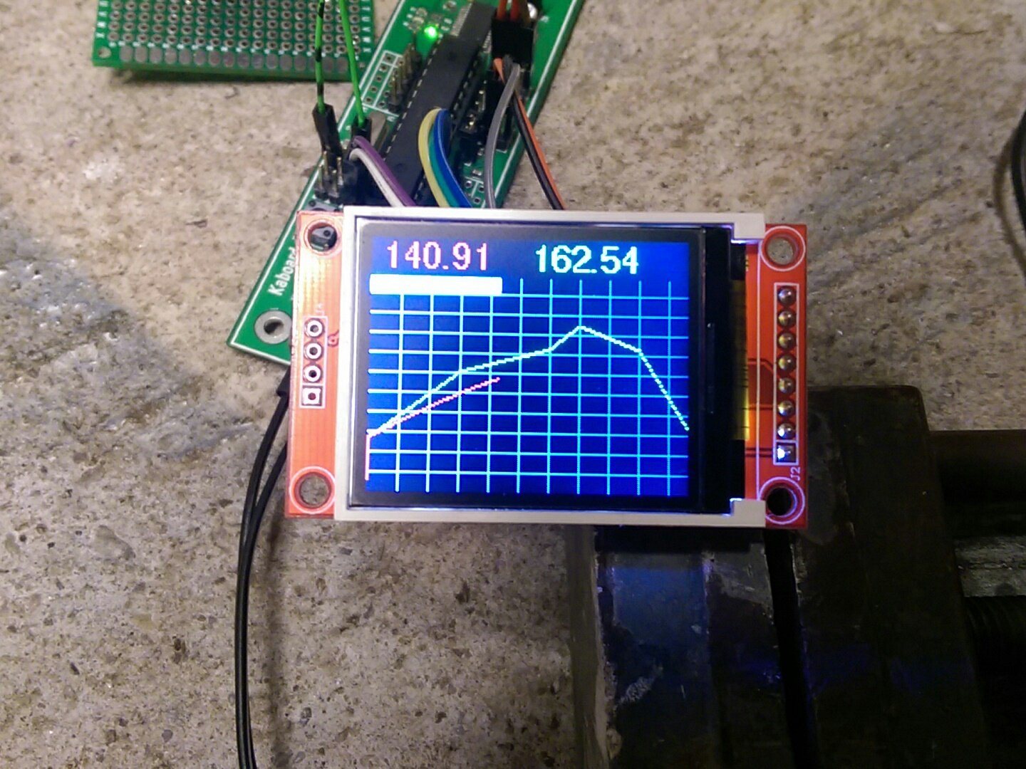
After that I gave the 2m bandpass a quick test using my noise source and an rtlsdr.
I would have preferred the pass band to start at a little higher frequencies, but other than that it looks pretty okay.
It should still attenuate most of the FM radio broadcasts, it’s probably alright.
The 70cm part will be tested as soon as the missing parts arrive.
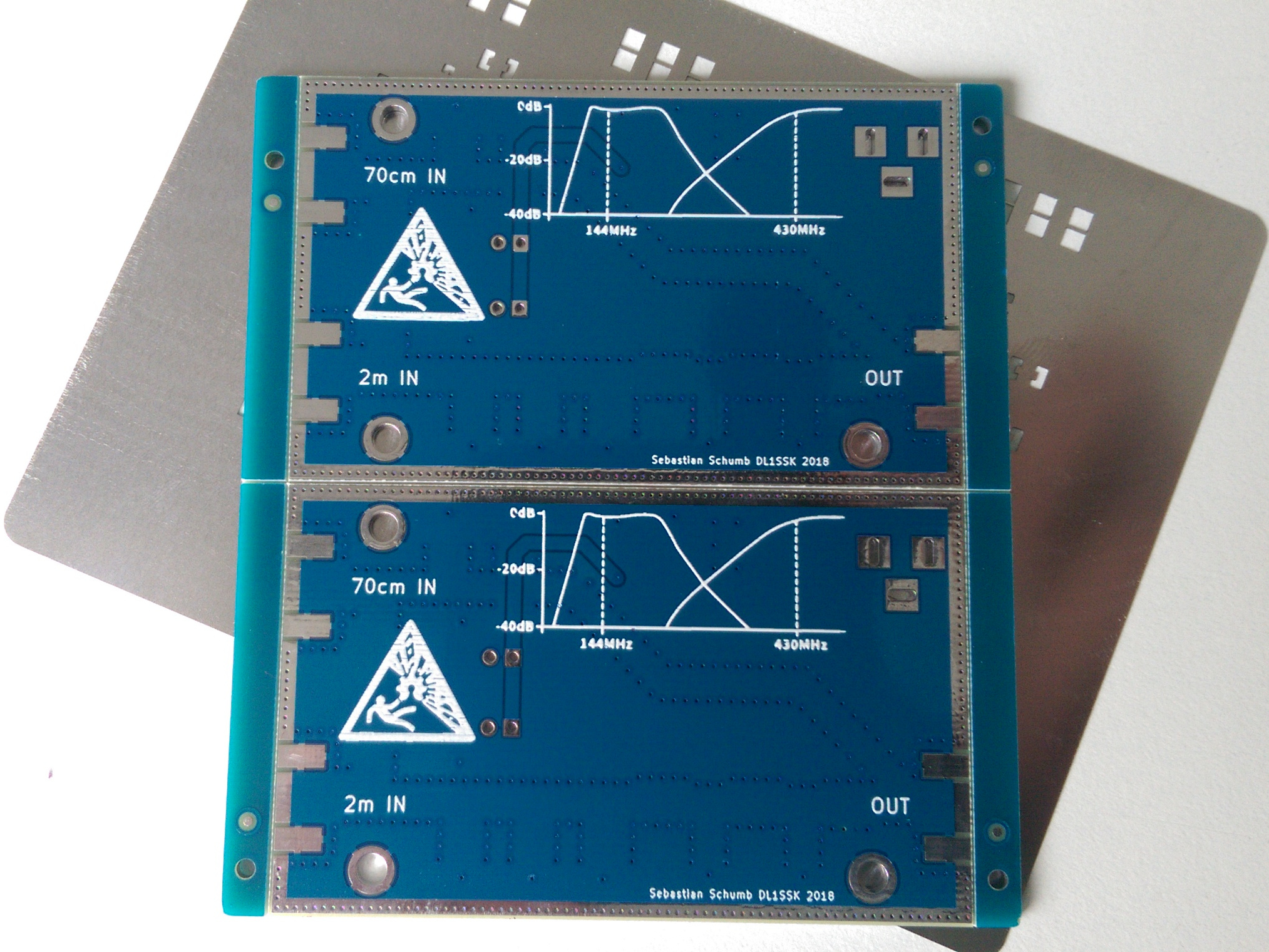
And last but not least: The board perfectly fits the aluminum case I found on ebay.
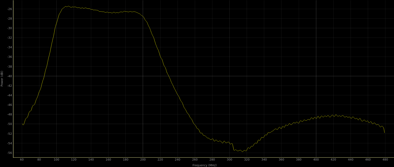
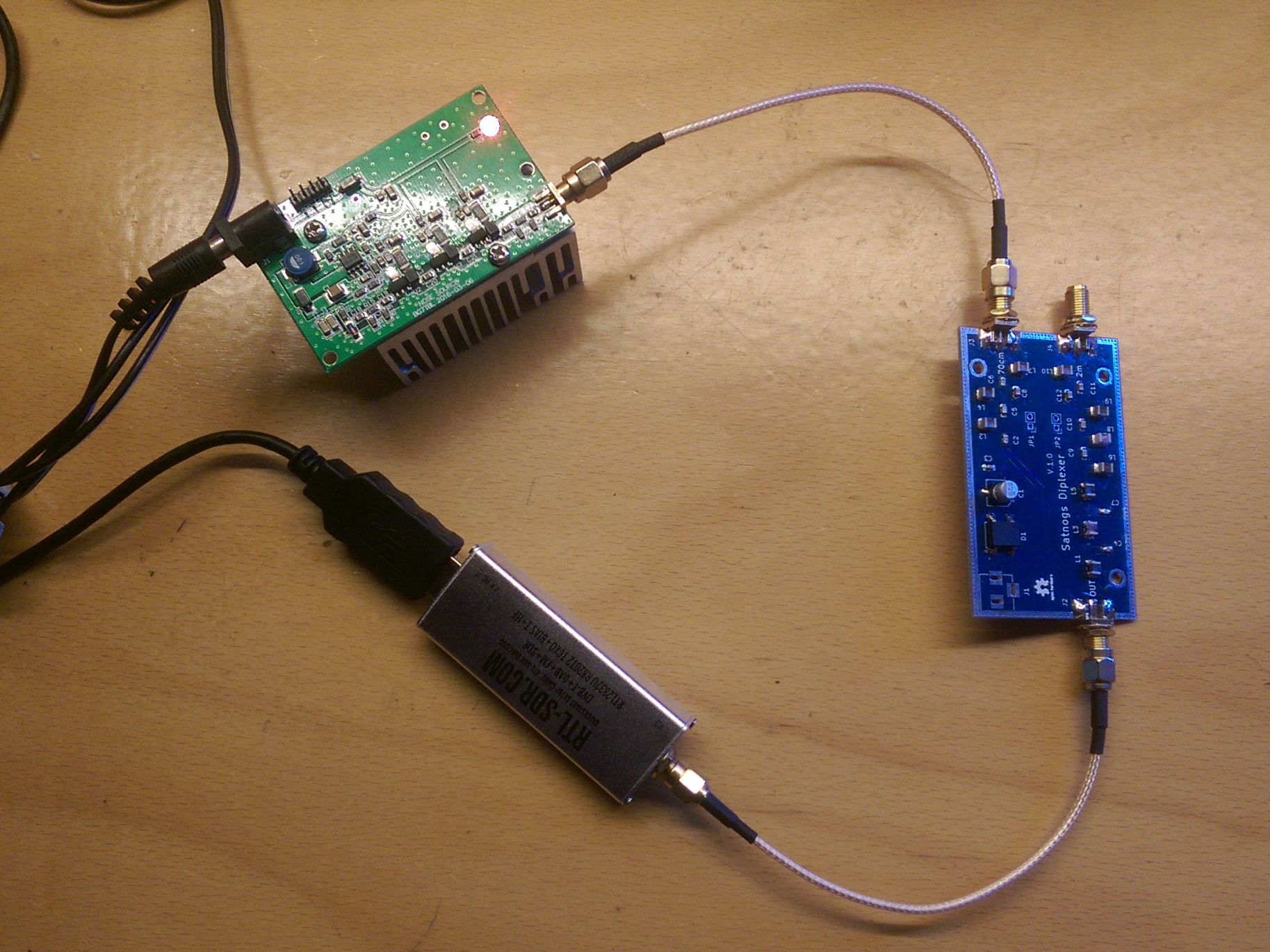
Today I’ve finally got the all missing parts to complete my two prototype boards.
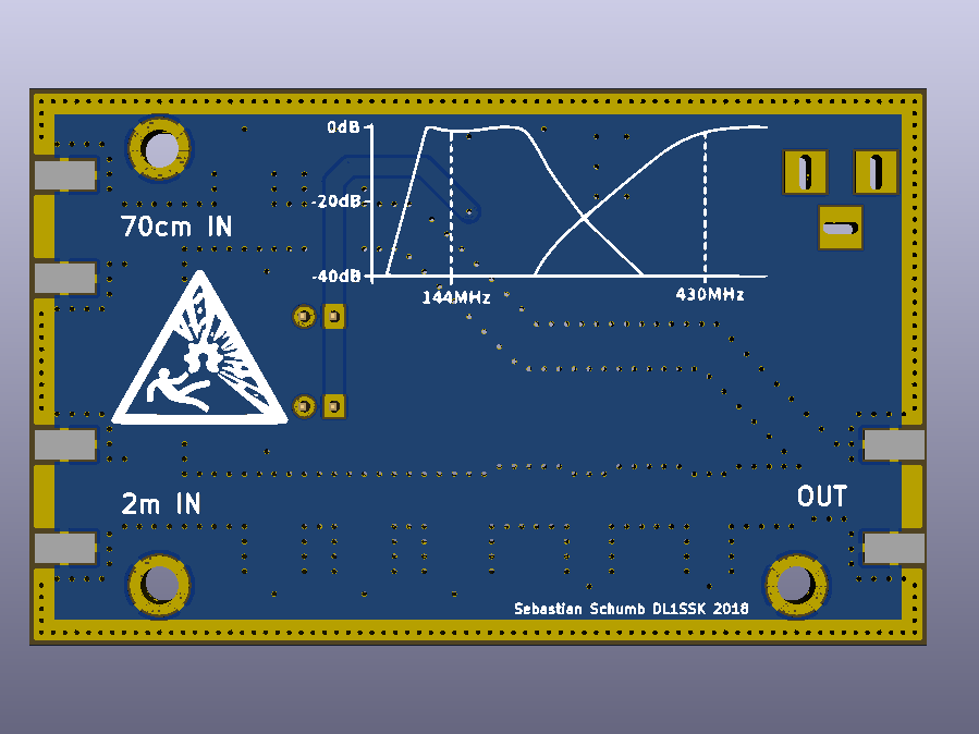
I used my hackish rtlsdr + noise source + qspectrumanalyzer setup to get a rough idea about its characteristic.
Since the combination of noise source and rtlsdr does not really produce an even spectrum over the 420MHz span, I took some baseline measurements and used some slightly questionable math to straighten it out.
So I still need a proper measurement with proper equipment.
It does look a lot like the simulation, though.
Most importantly the path between the two inputs has a high attenuation all the way through the spectrum.
Looks like it could work.
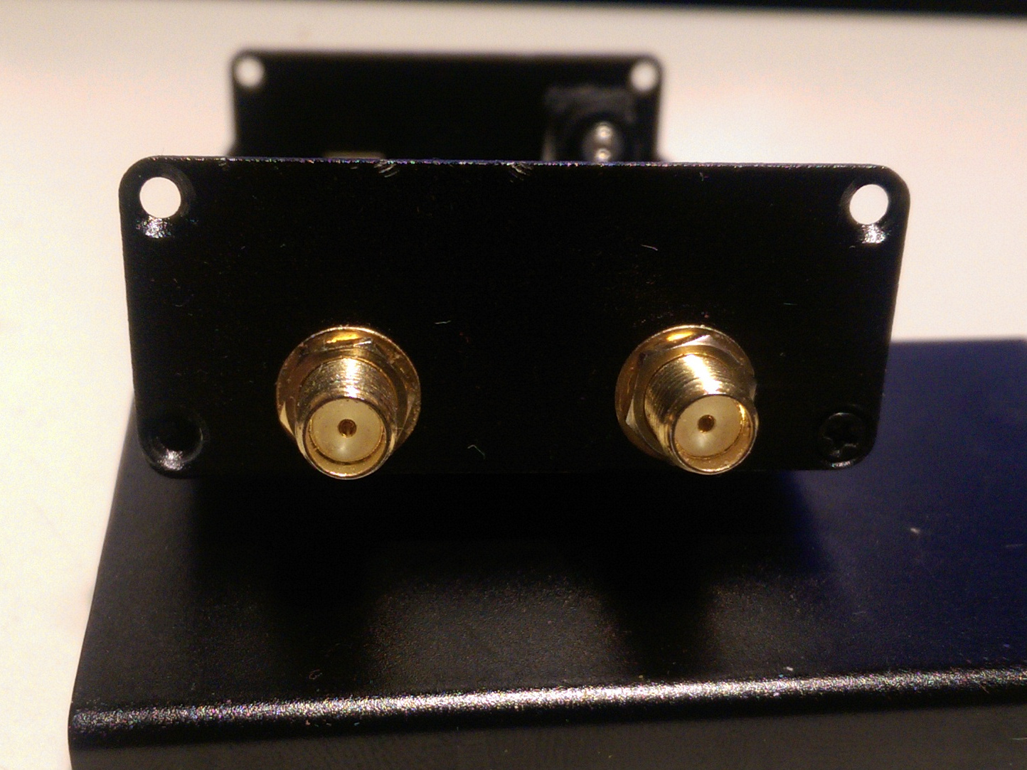
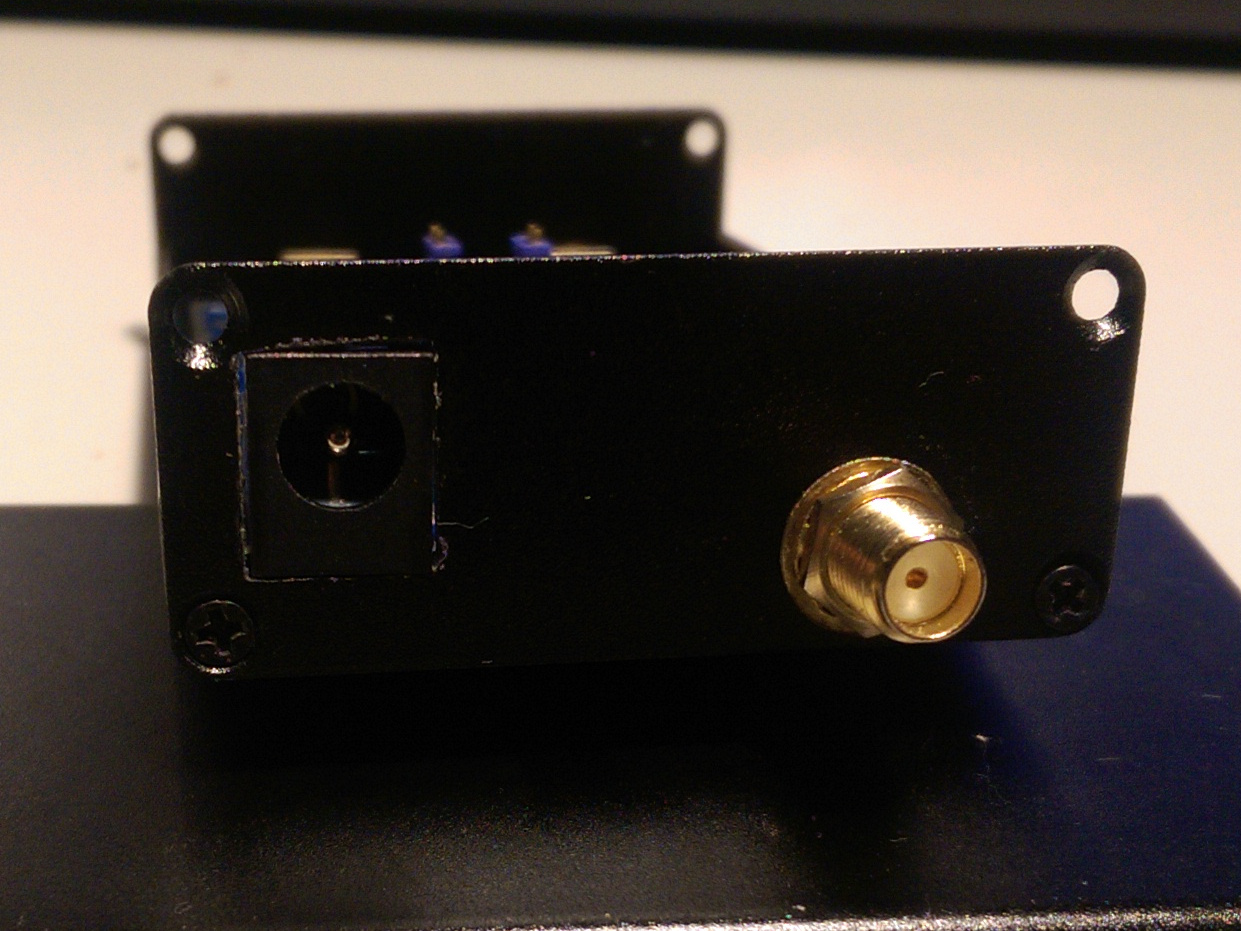
I’ve just put one of the two prototype pcbs into my enclosure.
As you can see in last photo 1) my CNC mill is still broken, 2) I only found the crappy files and 3) I’m really not that great a filing square holes.
On the bright side it fits perfectly into the box and once I closed it looks rather professional,
at least from 5 of its 6 sides.
I might laser engrave labels for the inputs, outputs and the frequency response into the top half next time somebody lets me near a lasercutter.
The next task is to get my reflow oven back up to speed so that I can populate the rest of the PCBs and hopefully everyone who asked can get one (that is a populated PCB, I don’t want to go through the trouble of preparing more enclosures).
Hi, I am interested for one PCB.
And if its posible upgrade for 23cm port.
73 Mili YT2CQ
Hi,
first of all sorry for going radio silent for a month.
I’ve just started a working full time, which as it turns out is a real full time job.
To cut the long story short every weird bug or hardware failure tends to end up on my desk and everything turns out more complicated the initially anticipated.
On the plus side I get work on energy management systems that help to make better use of renewable energy source, so at least I can help saving the planet a little.
On top of that I’m organizing C3Space, an assembly for space topics at the 35C3.
I’m also working on a cheap rotorless Satnogs GS that I’ll show off there.
So I’m running a little low on free time.
I’m planning to pick up the diplexer things in january.
So I’ve made a list with everyone who wanted a board,
and I should have enough make a fully populated diplexer for everyone.
Good news everyone:
I was able the meet the person behind kitspace.org at the 35C3, and with a little help from him I was able to make to make the diplexer avaialable on kitspace.
So it is trivial to order the parts and pcbs in case anyone urgently wants to build a diplexer themselves right now.
This looks really cool. Thanks for sharing it. One thing I notice is that the schematic displayed on the Kitspace page (and also the repo page) does not appear to be the most recent schematic. Something you may want to update.
Would care to elaborate?
As far as I can tell from the git history, qucs file never changed after the png was exported from it.
The png of the schematic does not include the jumpers and stuff for the bias-t circuit. Perhaps that is intentional, but that’s why I made the comment.