The available satellites/transmitters is filtered based on the frequency range of the antennas on the station. Having a S-band only station automatically does this. a bit of a drawback on stations with multiple antennas.
Hello, may I ask which antenna scaffolding model did you print?
And I used the RHCP 2.2 GHz version as I’m not using a dish. I have also build a second 2.2 GHz Helix “free hand” without the scaffolding mode - it works just as good.
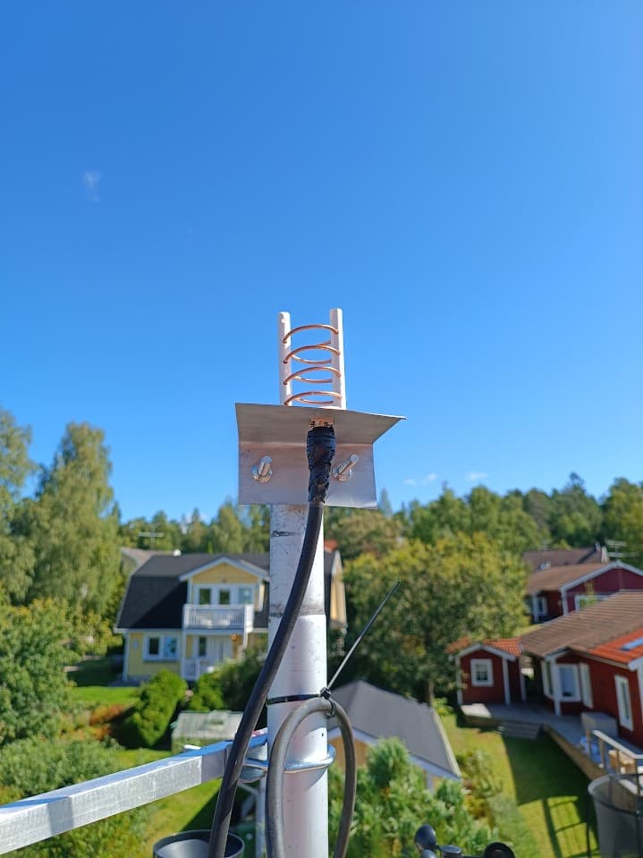
/Lars
5 Likes
Hello, I’m building a similar setup to @SM0TGU using the helical antenna scaffold from sgcderek, TQP3M9037-LNA and a HackRF One.
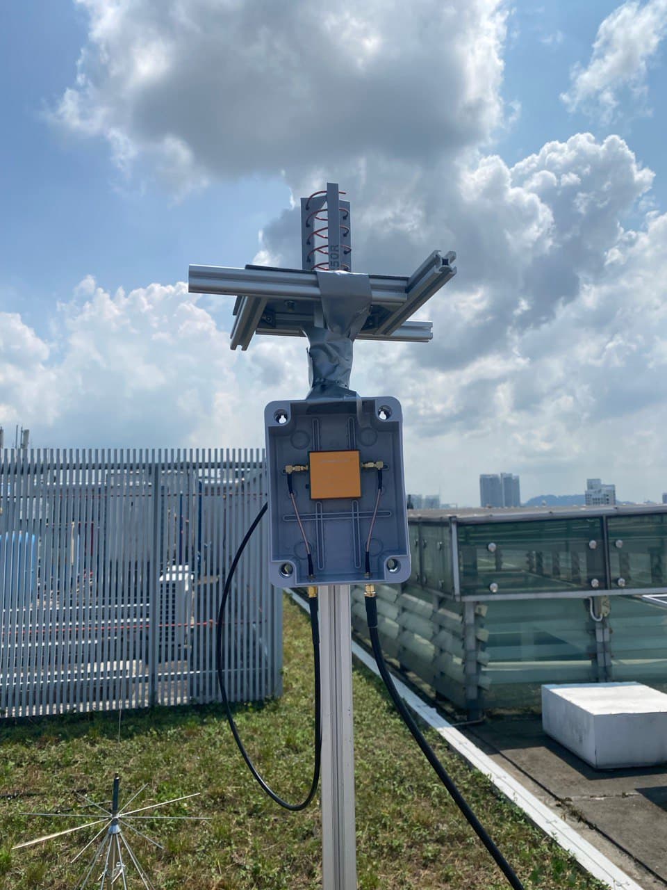
I tried a few observations but have not been able to receive anything so far. Most of my observations were with the LNA in BAT setting @SA2KNG thanks for finding the strange behaviour of the LNA! This is my only observation with the LNA in USB setting: SatNOGS Network - Observation 11862282
I tested the antenna using a VNA too and the dips were nowhere near 2.2GHz to 2.3 GHz (markers 1, M3, M2)
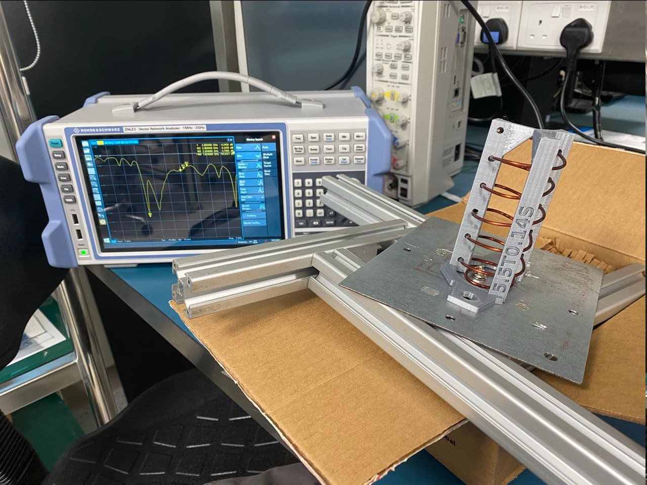
How should I fix my antenna?
How should I tune the different gain settings on my HackRF One?
And any other changes I should try?
1 Like
I found more observations done with the LNA in USB setting as well as a S-Band Pass filter F-BPSX-7035 (2200-2300MHz)
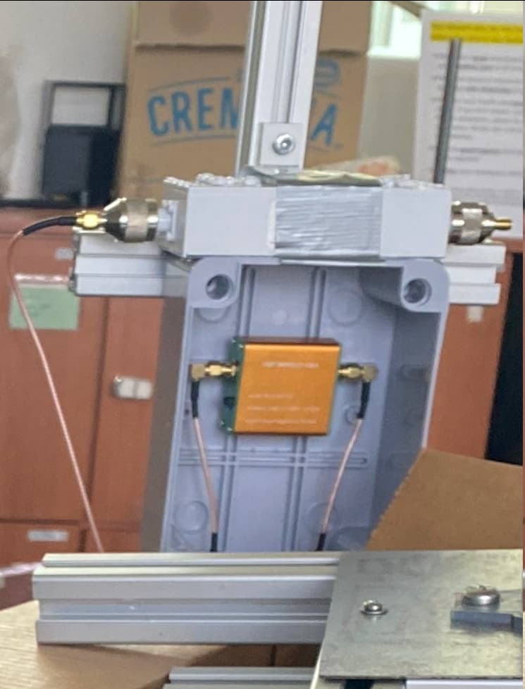
With “AMP=0,LNA=40,VGA=32”
https://network.satnogs.org/observations/11913452/
SatNOGS Network - Observation 11913454 (Hayang 1D)
With “AMP=14,LNA=24,VGA=34”
https://network.satnogs.org/observations/11913461/
https://network.satnogs.org/observations/11913685/
A few shots while starting up with my first morning coffee…
Welcome and nice to see the efforts to get another S-band station up and running!
None of your mentioned OBS show a valid observation, let me show you one as example https://network.satnogs.org/observations/11633077/ which looks nothing like your results.
I think With “AMP=14,LNA=32,VGA=26" should be a good start, but I also can not find how your pre-amp is powered. There’s no USB power cable on the amplifier, and , I use the same model, they can be powered from the HackRF but that is a setting you have to enable to get 3.3 volt on your antenna connector, and that’s not the AMP=14 setting…
The resonance frequency image for me does not show readable results about the frequencies, but on the image it looks like your connector on the base plate has the center pin quite high as starting point from which the helical goed down to run a bit in parallel to the base plate. It might help to solder a small piece of copper foil in paraller to the first 2 - 3 cm of the first turn to match a bit. The resonance frequency is set by diameter and distance and not the number of thurns so it should match 
Let me re-read your metadata and check where power for the LNA can be enabled (and should be checked on the center pin of the HackRF because the output mosfet is easy to kill)
brb
Ben
From: Software Defined Radio - SatNOGS Wiki
To activate bias-T power on the antenna port:
SATNOGS_DEV_ARGS=bias_tx=true
Which looks like a TX setting but actually powers the 3v3 on the antenna connector
Good morning  Thanks for the tips!
I am powering the LNA using the hackrf by running a pre observation script that runs hackrf_biast -b 1, the blue LED on the LNA lights up during observations (including the ones I linked earlier). The SATNOGS_DEV_ARGS=bias_tx=true didn’t work for me.
Do you mean something like this? (I’m using aluminium foil for demonstration)
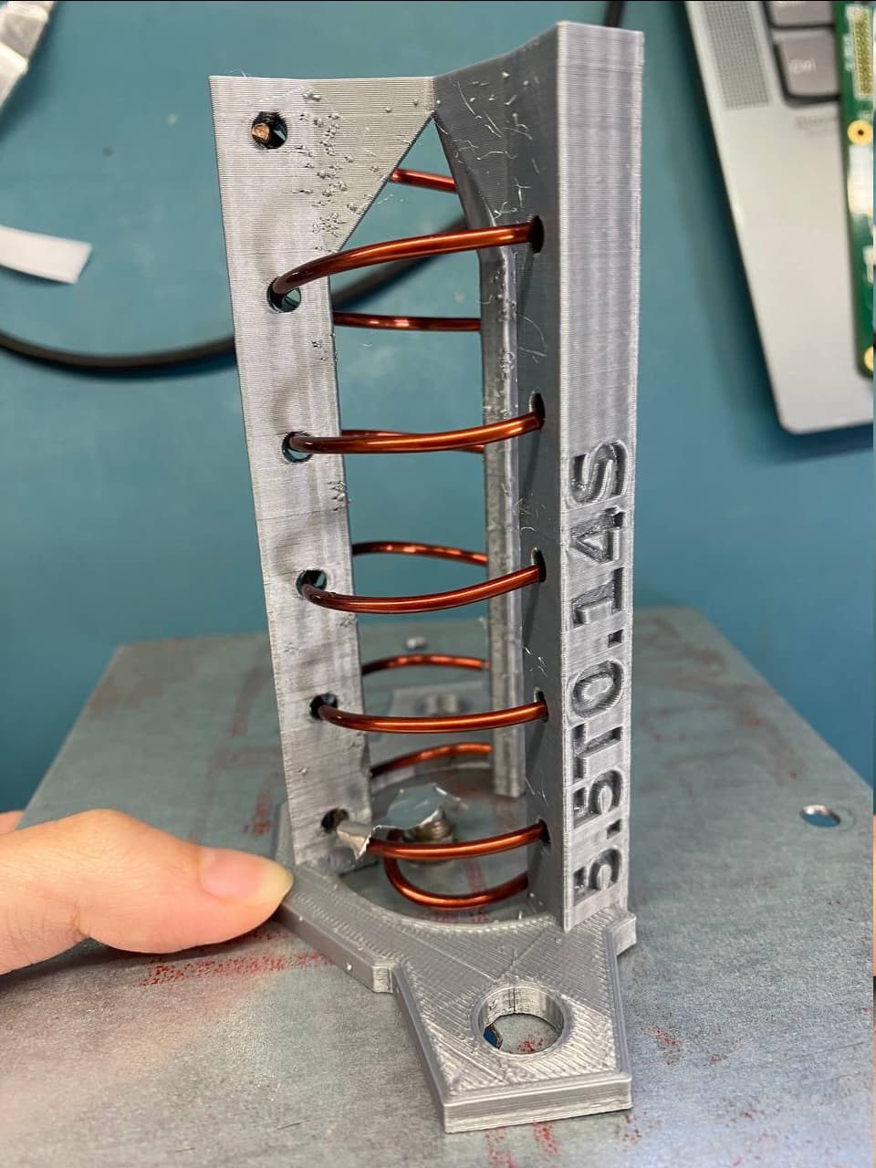
The VNA was not calibrated before I measured  but the lowest marker 1.65GHz, and the group of markers together where 2.2GHz, 2.25GHz and 2.3GHz, the whole range of the graph was from 1GHz to 3GHz
Here are some more close up photos of the antenna:
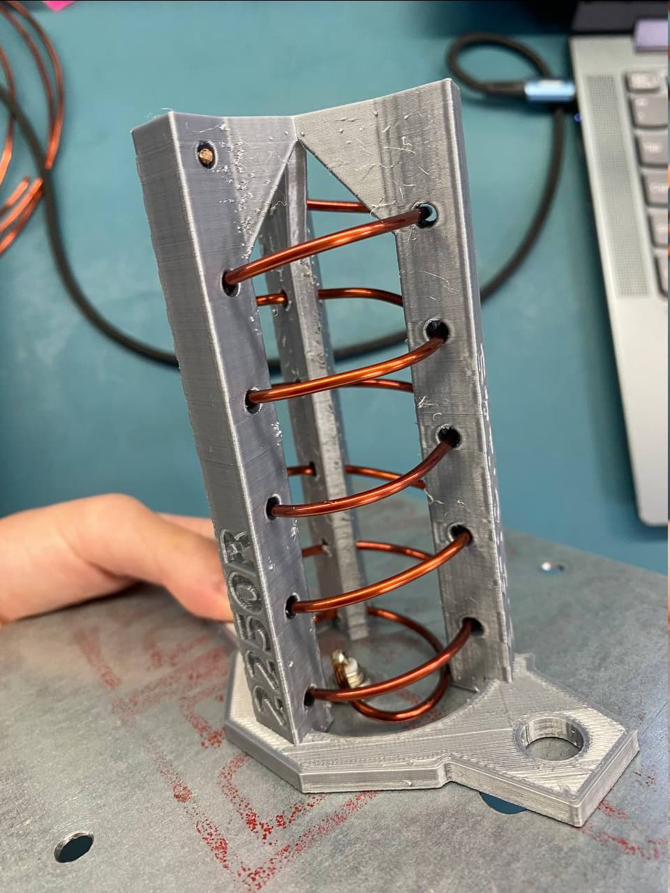
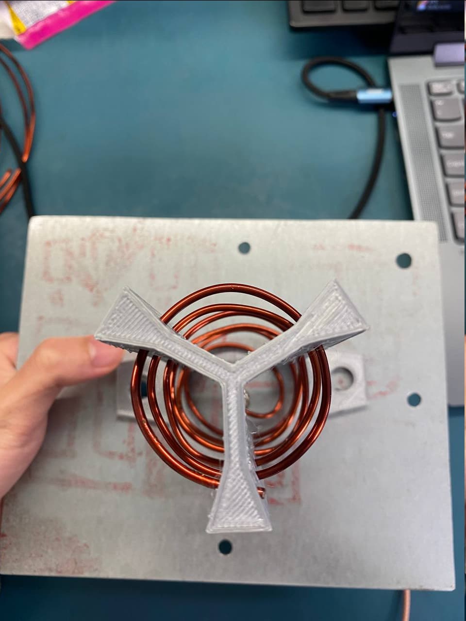
Thank you so much for your help!
The aluminium example is not what I meant.
two random webpages
https://3g-aerial.biz/en/online-calculations/antenna-calculations/helical-antenna-online-calculator
show what it’s meant to look like. To be honest, I did not do it the way shown in these 2 URL’s, my matching triangle is horizontally mounted to the first quarter turn, so in parallel with the ground reflector, in my case isolated with either teflon foil or Mica and has short distance to the ground plate (2 mm or a bit less)
Your wire looks like covered with emaille ? Did you check for continuity between the center antenne connector pin and the core on top of the antenna ?
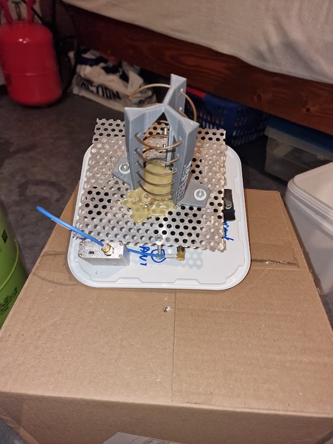
My Station 1433 S-band bucket antenna, has no impedance “tab” but I pushed the first part of the first turn almost as low as possible and hotglued it.
1 Like
Hi,
as Ben pointed out, the matching and also the big connector are two issues. I’d say you should still get a signal, but not optimal.
I have some pics of my builds over at my gdrive.
Regarding the biasing, I remember also using a script to enable the rx bias, as it wasn’t reset by the initialization of the flowgraph.
AMP should be 0 as the built in lna is extremely prone to dying and then blocking the signal.
One good thing on obs 11913452 is that there’s spurs or terrestrial signals present and not just a flat waterfall, it is a start (:
1 Like
Hello @clj55
Nice that you will become QRV on 2 GHz on SatNOGS. I have noticed that is very hard to get good RX on 2 GHz S-band with a simple Helix and not tracking antenna (without rotor control). It is also very hard to know what satellite is transmitting.
I had got a lot of help from @SA2KNG and yesterday I scheduled the satellite Odin on my station and Daniels. You can see the result here:
https://network.satnogs.org/observations/?sat_id=KISQ-1649-3429-8169-4287&start=2025-07-09+15%3A49&end=2025-07-11+15%3A59&observer=1643&station=&transmitter_mode=&transmitter_uuid=XXioskkLUpe75GsJKcatMD&experimental_observation=
I think (but note sure) that your can see a carrier from the Odin satellite. It is visible in both my station and Daniels.
Yeah, pretty sure. iirc it is ground locked so doesn’t follow a straight vertical line.
1 Like
Hi.
I have quite good RX on S-band with helical, bandpassfilter and preamp in a bucket on my roof. Signal is divided to 2 receivers, one for STRF and one for station 1433.
Is it possible that your reply about the helix has something to do with the satellite passes being not much “overhead” in Sweden and Norway, and if, would you profit from pointing the Helix antenna to some 45 degrees elevation towards South ?
Yes, that is something I might test later to change the elevation.
1 Like
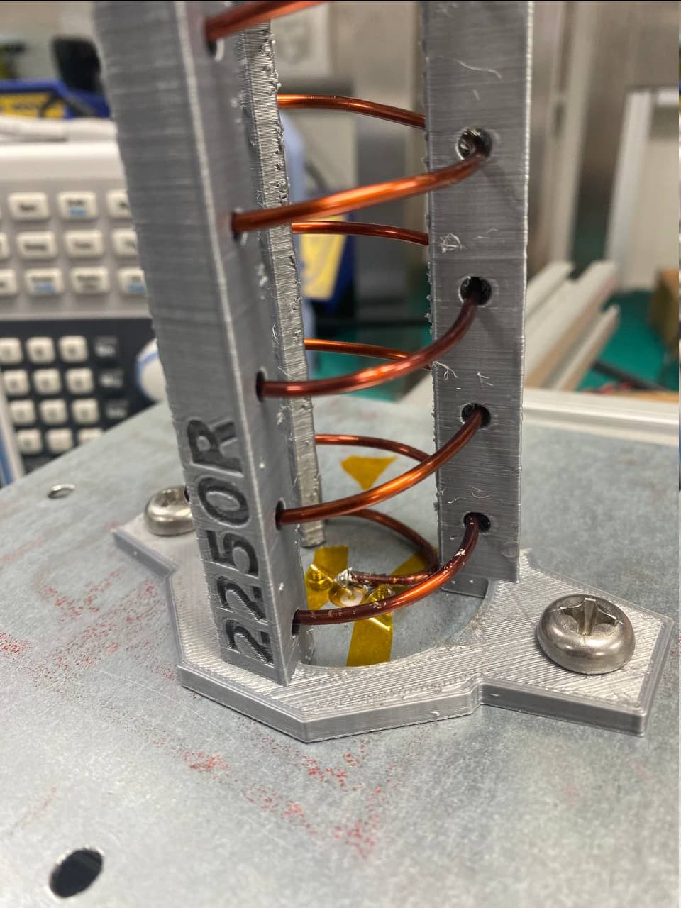
Hi, thanks everyone for the tips! I managed to get observations with signals yesterday after swapping out the HackRF for a USRP B200 mini, maybe the HackRF was malfunctioning. I also followed @pe2bz and pushed the first turn as low as possible to the ground plane which improved the S11 from -6dB to -10dB
2 Likes
A bit nitpicking, but also educational. Regarding the matching, it’s best done gradually and in the correct direction.
There’s a few videos demonstrating impedance mismatch, but I quite like this one AT&T Archives: Similiarities of Wave Behavior (Bonus Edition) .
At 19:03 shows what happens when you connect two mismatching transmission lines, and at 24:00 they show the tapered one.
Which the helical antennas often implement, that is 50 to ~150 ohm in a gradual fashion, narrower gap or wider strip at the coax end and tapers off moving away from that into the coil.
3 Likes
https://network.satnogs.org/observations/12000702/
Nice catch, this is certainly not a strong satellite as shows in other obs and with your observation I can check the transmitter to confirmed
Did you use a UV spray to protect the antenna? And if so, what kind?
Montana Varnish Spray Gloss 400ml